Caution |
Step 1:

Step 2:

Step 3:

Step 4:
Step 5:

Step 6:

Diversion:
Step 7:
You now have a power and ground bus that looks like this:
| |||
Step 1: |
Press the phototransistor into the end of the holder having the flattened
side.
| ||
Step 2: |
Punch two small holes 0.1 inch appart in a piece of black paper tape.
Push the leads of your red LED through the holes with the sticky side
toward the body of the LED.
| ||
Step 3: |
Push the LED into the hole in the other end of the holder
and use the tape to hold it in place.
| ||
Step 4: |
Put a piece of black tape over the slot to keep out ambient light.
| ||
Step 5: |
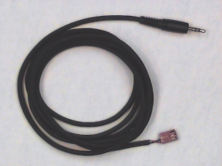
Plug a
phone plug patch cable
into J1-4 of the interface board.
Plug the LED into the 3-pin connector on the other end,
connecting the long lead (anode) to the
pin nearest the white stripe
and the short lead (cathode) to the
center pin.
If you have one of the cables with the covered connector, here's
how it's wired:
| ||
Step 6: |
Plug another phone plug patch cable
into J1-5 of the interface board.
Plug the phototransistor into the 3-pin connector on the other
end, connecting the long lead (emitter) to the
pin with the white stripe
and the
short lead (collector) to the
center pin.
black wire.
| ||
Diversion: |
As in the previous Lab we used the +20V
power supply
as a signal source.
We will be using the other half (0-6V) as a source
of power for our circuits.
Since we will need to have the power voltage
(and ground) available at many points in the circuit,
it will be convenient to connect them to the bus strips
that run through the breadboard.
| ||
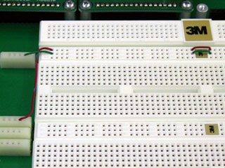
Step 7: |
Connect
one of the 4-pin terminal strips labeled
Gnd
on the breadboard to
the
center
row of the top bus strip.
Connect
one of the terminals labeled
+15V
to the
upper
row.
Connect the gaps at the center of the bus strip to form two
full width power buses.
You now have a power and ground bus that looks like this: |
![\includegraphics[scale=0.650000]{pwr_bus7.ps}](img200.png)
|
| ||
Step 8: |
Set the
METER SELECTOR
switch on the power supply to
6V.
Adjust the
0 to 6V
voltage control to produce 5 volts.
| |
Step 9: |
Use a red banana patch cord to connect the
0 to 6V Plus
terminal of the power supply to the red
banana jack
on the breadboard.
(This jack is labeled
+15V,
but for this experiment we will use it to supply 5 volts.)
With a green cord, connect the
0 to 6V Minus
terminal to the green
banana jack.
| |
Step 10: |
Plug your BNC-banana adapter into the
COMMON
and
0 TO +20V
terminals of the power supply, with the ground bump in the
COMMON
terminal.

| |
Step 11: |
Plug a BNC patch cord into this adapter and connect the other end
to J1-3 on the interface board.
This will bring the output of the 20 V supply to pin 3
on the interface board socket strip.
| |
Step 12: |
Wire the following circuit. The numbers on the connector symbols ( ) are the pin numbers on the interface connector socket strip (P10). |
![\includegraphics[scale=0.500000]{ckt3.2.ps}](img202.png)
It might look something like this:

| ||
Step 13: |
Set the
METER SELECTOR switch to the
+20V
position.
Vary the supply voltage
(as read by the front panel meter)
between 0 and 20 volts in steps of 2 V.
At each step measure (with the DMM) and record the voltage
across each of the two resistors.
| |
Step 14: |
From your measurements, compute the current through both the LED and the phototransistor. Make a plot of the phototransistor current vs. the LED current. Is it a straight line as we expect? |