| |
|

|
Step 4: |
|
Connect
CH1
of the scope to the collector of the phototransistor ( ).
).
|
Step 5: |
|
Turn the disk with your finger.
The signal should switch back and forth between 0 and 5 V.
|
Step 6: |
|
Turn off the power supply.
|
Note: |
|
The following three steps
recreate the setup for measuring the motor voltage
which was used in Experiment 1.
|
Step 7: |
|
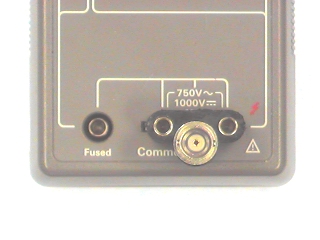
Set the DMM to DC Volts.
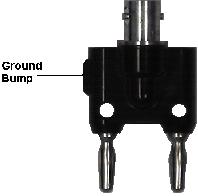
Remove the probes from the DMM and replace them with your
BNC-banana adapter.
Make sure the ground bump is toward the left.
|
Step 8: |
|
Plug a BNC clip lead into the adapter and connect the clips to the
terminals of the motor.
|
Step 9: |
|
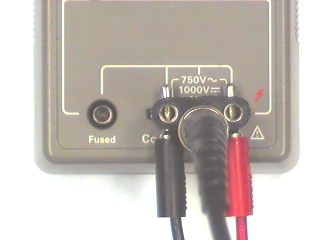
Plug a black banana patch cord into the
COMMON
terminal of the power supply (blue binding post).
Plug the other end into the left hand hole in the BNC-banana adapter.
Plug a red banana patch cord into the
0 TO +20V
terminal of the power supply.
Plug the other end into the right hand hole in the BNC-banana adapter.
|
Step 10: |
|
Turn on the power supply and adjust the
0 to 20V
output to 20 V.
|
Step 11: |
|
Measure the frequency of the waveform on the scope.
Since there are 12 holes in the disk, this will be 12 times
the rotational rate of the motor.
Divide this by 12 to get the frequency of rotation of the motor in Hz.
To get the speed in RPM, multiply the frequency in Hz. by 60.
As before, you should get a number between 5000 and 6000 RPM.
|
Step 12: |
|
Reduce the voltage in 2 V steps until the motor stops running.
At each step, measure the speed of the motor and record
the voltage and the speed.
|
Step 13: |
|
Plot the motor speed vs. voltage.
You should get
the same curve as in Lab 1, i.e.
a straight line which crosses the x-axis
at around 1 or 2 volts.
|
Step 14: |
|
Compute the slope of this line.
Compare this to the result you got in Lab 1.
|

![\includegraphics[scale=0.500000]{ckt3.1.ps}](img203.png)