| |
|

|
Step 1: |
|
Set the output of the 0-6 V power supply to 4 V.
Turn off the supply.
|
Step 2: |
|
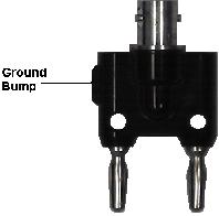
Plug your
BNC-banana adapter
into the 6V supply terminals.
Be sure that the prong with the ground bump is plugged
into the negative (black) terminal of the power supply.
|
Step 3: |
|
Plug one end of a BNC patch cord into the adapter.
Plug the other end into J1-3 on the interface board.
|
Step 4: |
|
The motor is connected to pins 20 and 21 of the interface board
socket strip.
Connect pin 21 to ground and pin 20 to the positive terminal
of the 0-6 V power supply (pin 3 on the socket strip).
|
Step 5: |
|
Plug the camera cable into J2-1 on the interface board.
|
Step 6: |
|
Turn on the power supply.
Verify that the disk is rotating in a clockwise direction as
seen from the front of the camera.
If it is rotating counterclockwise, reverse the two connections
to the motor.
|
Step 7: |
|
Turn off the power supply.
|
| |
|
|
Step 1: |
|
Plug the cable from the LED on the front of the camera into J2-2 on the interface board.
|
Step 2: |
|
Wire
the following circuit.
Remember to connect power to the opamp.
![\includegraphics[scale=0.650000]{ckt10.5.ps}](img254.png)
|
Question 2: |
|
Explain how the above circuit works.
|
Step 3: |
|
Connect  to the
MAIN
output of the function generator.
to the
MAIN
output of the function generator.
|
Step 4: |
|
Set the function generator to produce a 30 Hz
1 V p-p sine wave.
|
Step 5: |
|
Turn on the power and look into the receiver eyepiece.
You should see alternating red and black bands moving across the
image.
|
Step 6: |
|
Vary the
AMPLITUDE
and
DC OFFSET
controls.
What effect do they have on the image.
|
Step 7: |
|
Reset the
AMPLITUDE
and
DC OFFSET
controls to produce a bright band and a dark band of equal
width.
Increase the frequency while watching the pattern.
What is the maximum frequency that produces a visible pattern?
|
Question 3: |
|
Explain the various patterns you have seen in this part.
|
![\includegraphics[scale=0.500000]{ckt10.1.ps}](img252.png)
![\includegraphics[scale=0.650000]{ckt10.2.ps}](img253.png)