We need to do two things: convert the output to current, and make the pulses narrower. We will use the internal resistance of the function generator to limit the current. We will use the duty cycle control to make the pulses narrower.
In Question 1 you considered what would happen if you were to connect an LED directly to an ideal voltage source. Although the power supply is very close to being an ideal voltage source, the function generator is not. According to its specifications it has an output impedance of 50 ohms. That means that it can be modeled as an ideal voltage source in series with a 50 ohm resistor. So if you were to connect the function generator directly to the LED you would have the following circuit:
For our stroboscope, we want the LED to be as bright as possible (without destroying it). According to the package, the maximum rated forward current for the LED is 50 mA.
|
| ||
Step 1: |
From your measurements in the previous experiment,
estimate the forward voltage of the LED which corresponds to
a current of 50 mA.
Add to this the voltage drop across the 50 ohm internal resistance
of the function generator
at a current of 50 mA.
This will be the peak
open-circuit
value of the function generator voltage.
Call this value | |
Step 2: |
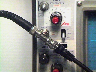
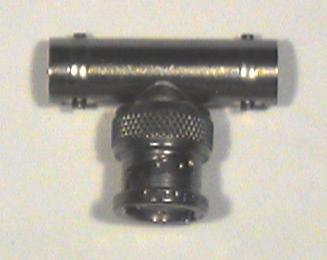
Connect your
BNC T connector
to
CH1
of the scope.
| |
Step 3: |
Use a BNC patch cord to connect one end of the T to the
function generator output.
Connect a BNC clip lead to the other end of the T.
| |
Step 4: |
Set the function generator to produce a 10 Hz
Square wave.
Adjust the
AMPLITUDE
control so that the peak-to-peak (p-p)
voltage is the twice the value you calculated above
(i.e. the signal alternates between | |
Step 5: |
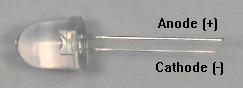
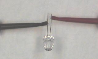
Connect the clip leads from the T connector to the LED.
Connect the positive (red) clip to the cathode (shorter lead)
and the negative (black) clip to the anode (longer lead) of the LED.
| |
Step 6: |
Rotate the DUTY control of the function generator fully clockwise. The rate of flashing should slow down and the length of the flashes should be much shorter than the off times. If the LED is on longer than it is off, reverse the leads. |
|
| ||
Step 1: |
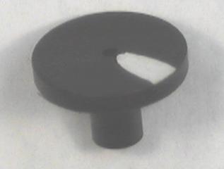
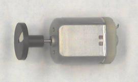
Get an
18 V motor
and a
strobe test disk
from the cart.
If they aren't already connected together, press the disk onto
the shaft of the motor with the large end outward.
| |
Step 2: |
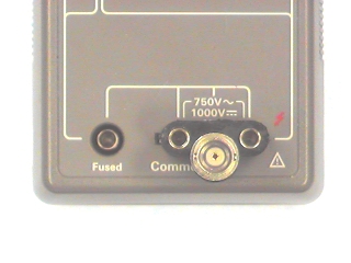
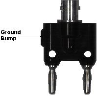
Set the DMM to DC Volts.
Remove the probes from the DMM and replace them with your
BNC-banana adapter.
Make sure the ground bump is
connected to the
COMMON
terminal of the DMM.
| |
Step 3: |
Plug a BNC clip lead into the adapter and connect the clips to the
terminals of the motor.
| |
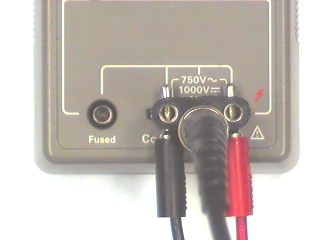
Step 4: |
Plug a black banana patch cord into the
COMMON
terminal of the power supply (blue binding post).
Plug the other end into the left hand hole in the BNC-banana adapter.
Plug a red banana patch cord into the
0 TO +20V
terminal of the power supply.
Plug the other end into the right hand hole in the BNC-banana adapter.
| |
Step 5: |
Because the diameter of the disk is greater than the width of the motor,
you can't set it down or it will rub on the bench top.
Either hold it firmly in your lab partner's hand, or wedge it between
the top shelf of the bench and the power supply, with the disk
hanging over the edge.
| |
Step 6: |
Turn on the power supply and slowly increase the voltage until
the motor begins to turn.
Note whether it's turning clockwise or counterclockwise.
Increase the voltage to 20 V.
| |
Step 7: |
Shine the flashing LED on the disk and adjust the frequency until
the disk appears to stop with only a single stripe.
Increase the frequency until you find the highest frequency
which will stop the disk with a single stripe.
This is the frequency of rotation of the motor.
| |
Step 8: |
The frequency displayed on the function generator will be in Hz.
Since motor speed is usually given in revolutions per minute (RPM),
multiply the frequency in Hz by 60 to get RPM.
You should get a number between 5000 and 6000 RPM.
If not, check your calculations and make sure you do not have
an aliased rate.
| |
Step 9: |
Slightly increase the frequency of the function generator
and verify that the image appears to rotate slowly in the opposite
direction from the actual rotation of the disk.
Slightly decrease the frequency and see that it rotates slowly in
the same direction.
| |
Step 10: |
Reduce the voltage in 2 V steps until the motor stops running.
At each step, measure the speed of the motor and record
the voltage and the speed.
| |
Step 11: |
Plot the motor speed vs. voltage.
You should get a straight line which crosses the x-axis
at around 1 or 2 volts.
| |
Step 12: |
Compute the slope of this line.
How?
| |
Step 13: |
Reverse the wires from the power supply to the motor.
Verify that the motor runs in the opposite direction.
| |
Question 2: |
How effective is the LED stroboscope as a tool for measuring speed? Suggest ways in which it could be improved. |