![\includegraphics[scale=0.640000]{ckt8.2.5.ps}](img251.png)
Fig. 8.2: TCA0372
The low output current of the D/A converter and the 741 op amp has restricted the physical processes we are able to control. An op amp with higher output current will allow us to drive more power hungry devices, such as motors.
The TCA0372 has a maximum output current of 1 A (which is also the limit of the power supply). It is a dual op amp (i.e. two op amps in the same package) so obviously it can't have the same pinout as the 741. We will only use one half of the package, so here are the pins we will use:
So far we have always used dual power supplies (+15 V and -15 V) with our op amp circuits. This has allowed us to produce outputs which can be either positive or negative. Many devices (e.g. light bulbs, blower motors) only require inputs of a single polarity (typically positive). In this case the negative power supply is an unnecessary additional expense. Many op amps, including the TCA0372, are capable of being used with a single power supply.
![\includegraphics[scale=0.640000]{ckt8.2.1.ps}](img252.png)
![\includegraphics[scale=0.500000]{ckt8.2.3.ps}](img253.png)
|
| |||
Wiring: |
Connect
| ||
Testing: |
Set the function generator to produce
a 6 V p-p, 100 Hz sine wave with a 5 V offset
(i.e. a minimum value of 2 V and a maximum of 8 V).
Connect the function generator output to | ||
Observations: |
Measure the actual gain of the circuit. Increase the input amplitude until clipping of both the top and bottom of the waveform occurs. What are the minimum and maximum achievable output voltages? |
|
| ||
Wiring: |
Disconnect the power amplifier input from the function
generator and connect it to D/A output channel 1.
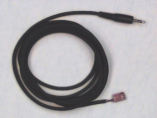
Plug the appropriate end of a
phone plug patch cable.
into
J2-2.
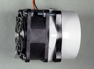
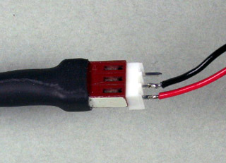
Plug the white, 3-pin plug on the fan motor into
the connector on the other end of the cable,
The red wire on the fan cable should be
on the same side as the white stripe on the patch cord connector.
Via the interface connector strip, connect the positive (red) terminal of the motor to the power amplifier output and the negative (black) terminal to ground. When you are finished, your system should look like this: ![\includegraphics[scale=0.500000]{ckt8.2.4.ps}](img254.png)
| |
Testing: |
Restart the Lab 8 VI.
On the tab labeled
Manual
increase the value of the slider labeled
Motor.
The fan should begin to turn, and run faster
as the slider value is increased.
Although an ordinary DC motor will run in reverse if the
polarity is reversed, the fan motors are
brushless
motors, which won't run at all if the polarity is incorrect.
If nothing happens, verify that
| |
Design Challenge: |
Devise a method for measuring the rotational speed of the fan, using components that you have worked with in the lab. |