If a thin diaphragm experiences a difference in pressure
between its two sides it will be deformed:
concave (compressive strain) on the high pressure side
and convex (tensile strain) on the low side.
If strain gages are placed at appropriate locations on
a such a diaphragm, the strains resulting from the
pressure differential will be translated
to changes in resistance which can be measured
with a bridge circuit.
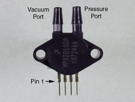
Ports for tubing are provided for each side of the diaphragm.
The port directly above pin 4 is the
positive pressure port ( ) while the one above
pin 1 is the vacuum port (
) while the one above
pin 1 is the vacuum port ( ).
).
| |
|

|
Wiring: |
|
Plug the MPX2010 into the breadboard
and connect it
to the INA126
as shown below.
![\includegraphics[scale=0.500000]{ckt8.1.3.ps}](img59.png)
Also connect  to A/D input channel 6.
Since the bridge circuit is less sensitive to changes
in the excitation voltage,
we won't explicitly monitor it like we did in Lab 4.
However, for maximum accuracy you should use your DMM
to set the power supply voltage to
exactly 15 V.
|
Testing: |
|
Monitor
with the oscilloscope set to 20mv/div, DC.
Press the tip of your finger against the pressure port of
the MPX2010. You should observe a positive signal on the scope.
Similarly, pressing your finger against the vacuum port
should produce a negative signal.
Connect
one end of
a 3' piece of 1/8" i.d. vinyl tubing to the
pressure port of the MPX2010.
Speak, whistle, or otherwise make noise at the other end.
You should observe an appropriate signal on the oscilloscope.
|
Measuring Pressure: |
|
Load the Lab 8 VI from the ELEC 243 Start menu.
The left-hand half of
this VI reads the amplified output of the pressure
sensor, converts the voltage into the equivalent
pressure, and displays the result.
We'll look at the right-hand half in the next Experiment.
Start the VI.
The value of the
Vin
indicator should correspond to the value
measured by the oscilloscope.
Since both ports are connected to the same pressure
(ambient atmospheric) this should be zero.
However, the amplifier input offset voltage and any
imbalance in the sensor bridge elements will
likely result in a non-zero value.
Wait a minute or two for things to warm up, then enter
the value of
Vin
into the
offset
control.
The displayed value of pressure should now be zero.
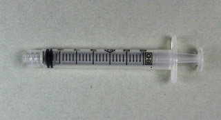
Draw the plunger of a
3 ml Syringe
to the 2 ml mark.
Insert the tip of the syringe into the free end of
the tubing connected to the pressure sensor.
Adjust the plunger until the pressure reads zero
and note its position.
Slowly press the plunger in until the pressure reading
is 10 kPa
and again note the position.
|
Question 1: |
|
Is the observed change in pressure consistent with the
change in volume? Explain.
|
Moving On: |
|
When finished with this Experiment, be sure to stop the VI.
|
![\includegraphics[scale=0.500000]{ckt8.1.1.ps}](img57.png)
 .
Choose the resistor from your parts kit which gives
a value for
.
Choose the resistor from your parts kit which gives
a value for ![\includegraphics[scale=0.500000]{ckt8.1.2.ps}](img58.png)