(Click to enlarge)
(Click to enlarge)
(Click to enlarge)
| 1. | Set the display resolution to 1680 x 1050 | |||
|---|---|---|---|---|
| This is not strictly necessary, but it is the only choice for display resolution which preserves the aspect ratio of the monitor. If you use any other resolution, circles will appear oval. | ||||
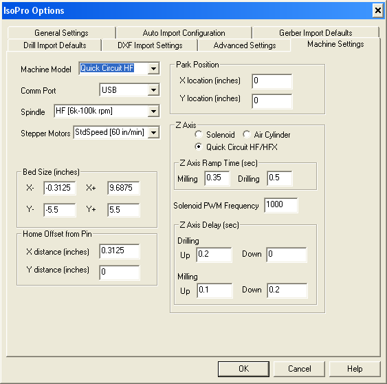
| 2. | Set machine parameters | |||
| The default hardware settings are for a different model from what we have. This means that nearly every parameter is wrong. Start IsoPro, select Preferences... from the Edit menu, and click on the Machine Settings tab. Change the appropriate fields until the panel looks like the snapshot on the right. In particular, be sure that you set the Machine Model, Comm Port, High Speed Spindle, Z Axis, and Z Axis Delay fields. |
(Click to enlarge) | |||
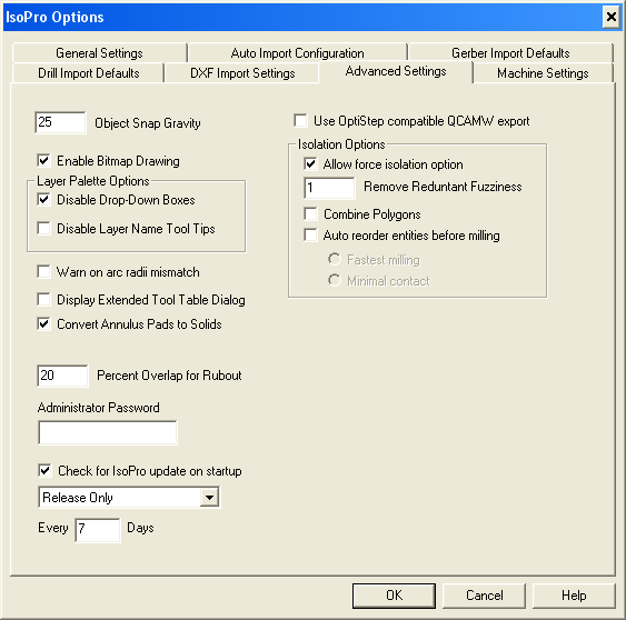
| 3. | Set isolation options | |||
| While still in the preferences dialog, click on the Advanced Settings tab. In the Isolation Options area check the Allow force isolation option box. This will prevent a bug in IsoPro from causing a crash when isolating boards built with the build_panel program. |
(Click to enlarge) | |||
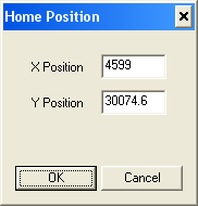
| 4. | Set origin | |||
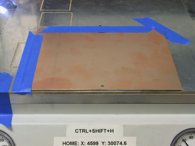
| After clicking OK on the Options dialog, type Ctrl-Shift-H on the keyboard. This will bring up the Home Position dialog. Enter the X and Y values that are taped to the front of the T-Tech machine and click OK. |
| |||
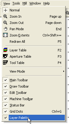
| 5. | Display Layer Palette. | |||
| Click on View in the menu bar. Click on the Layer Palette entry at the bottom of the menu, if it is not already checked. |
(Click to enlarge) | |||
| 1. | Set up directory structure | ||
|---|---|---|---|
| It is assumed that your pcb directory is structured as described in the PCB Layout Tutorial. This means that there will be a directory for each board you are planning to fabricate, and this directory contains the Gerber files and drill tape for the board. | |||
| 2. | Create Gerber and Drill files. | ||
| If you have not already done so generate the artwork and drill tape files for your board as described in the PCB Layout tutorial. | |||
| 3. | Copy build_panel program and associated files | ||
| Download the pcb.zip file and copy the files build_panel.exe and sample_panel.txt and the directories frame1 through frame4 into your pcb directory. These will be used to pre-process your artwork and drill files before sending them to IsoPro. |
| 1. | Assemble Boards into a Panel | |||
|---|---|---|---|---|
| The smallest practical blank board size for the T-Tech is 4.5 x 6 inches. This will produce a board of up to 3 x 3 inches, allowing for the border on the front and sides required to support the pressure foot. This means that between two and four of the smaller ELEC 332 breadboard modules can be combined into a single run in order to save time and material. There is a program (build_panel.exe) in the pcb.zip file which performs this function. Even if you are only milling a single board, you should run your files through the pre-processor: it will add the mounting and outline holes and it will correct for a misalignment in the T-Tech machine between the drill holes and the traces. | ||||
| To run this program, you need to prepare a control file defining the boards you wish to combine and how they are to be positioned. There is a commented example file (sample_panel.txt) included in the zip file which explains how to create this control file. Place this file in the root directory of your pcb directory structure and run the program from that directory with the control file name as the argument (e.g. build_panel sample_panel.txt). This will create a new directory (panel2 in the example) which contains two Gerber files and a drill file. These three files will be used as the input to the IsoPro program. | ||||
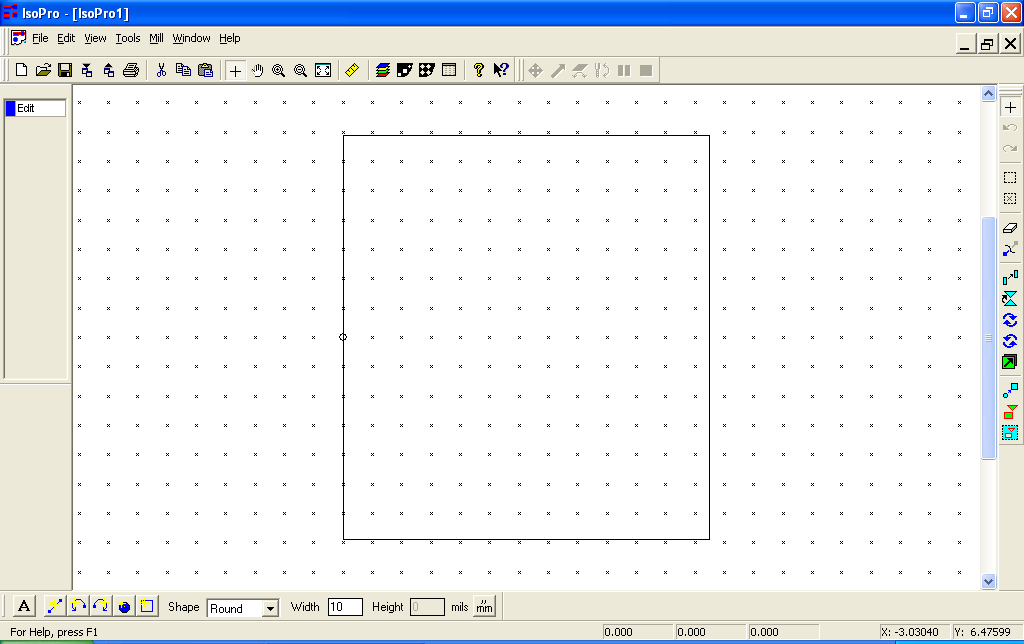
| 2. | Start IsoPro | |||
| You should see a display like this. The rectangle in the middle of the screen represents the working area of the milling machine. |
(Click to enlarge) | |||
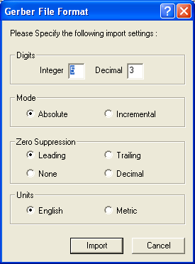
| 3. | Import Gerber files | |||
| Select File->Import->Gerber File(s)... from the menu bar. Browse to the directory where you asked build_panel to place its output, select top.gbr and bottom.gbr, and click Open. Accept the defaults and click Import. |
(Click to enlarge) | |||
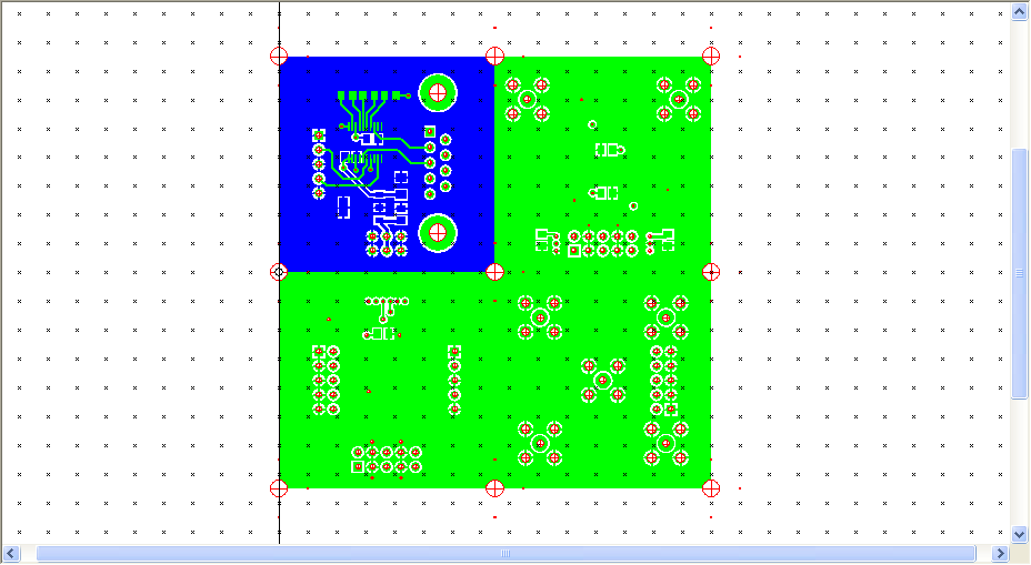
| 4. | Import drill file | |||
| Select File->Import->Drill File(s)... from the menu bar. Browse to your board directory, select holes.drl, and click Open. Again, accept the defaults and click Import. |

(Click to enlarge) | |||
| At this point your screen should look something like this. |
(Click to enlarge) | |||
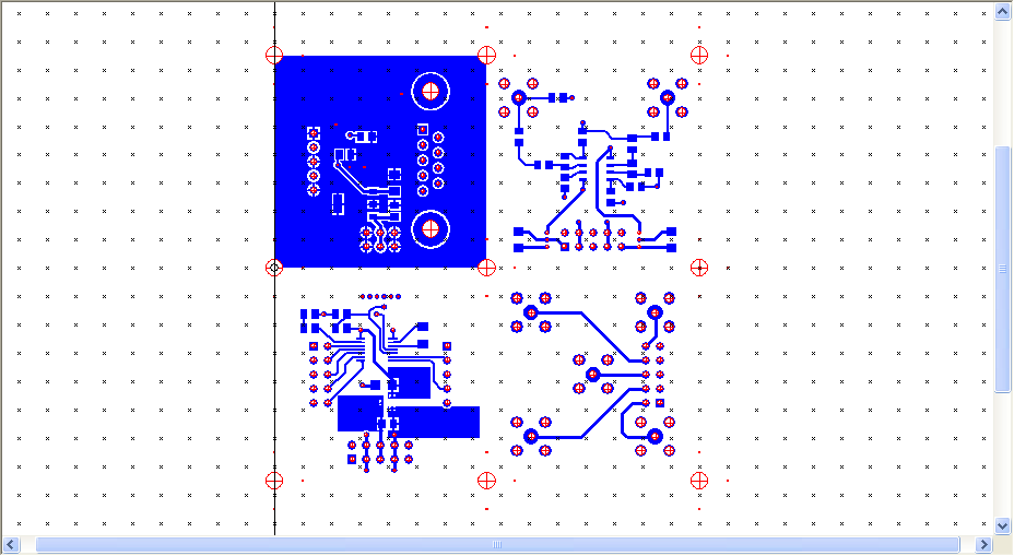
| 5. | Examine your data | |||
| Carefully examine the top and bottom layers, the drill holes, and their relationship to each other. Verify that everything is present, the right size, and in the right place. Unlike the layers in Cadence Allegro, the layers in IsoPro are not transparent. To view the hidden layers, click on the entry in the Layer Palette for the occluding layers until their status changes from view to hide. |
(Click to enlarge) | |||
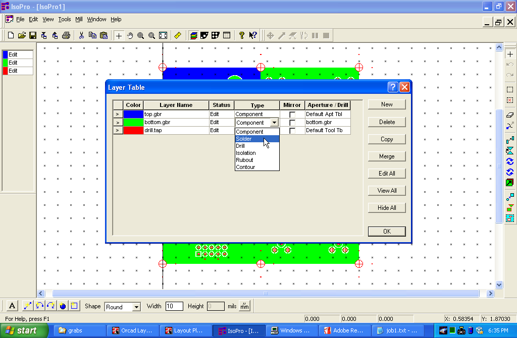
| 6. | Set up the layer table | |||
It is necessary to tell IsoPro which is the bottom layer
so that it will know to mirror the tool motions.
Click on the
Layer Table button
( )
to bring up the layer table.
Click on the
Type
field for bottom.gbr and select
Solder
from the drop-down list that appears.
Do not check the mirror box. This will be done automatically when you click
OK. )
to bring up the layer table.
Click on the
Type
field for bottom.gbr and select
Solder
from the drop-down list that appears.
Do not check the mirror box. This will be done automatically when you click
OK.
|
(Click to enlarge) | |||
| 7. | Run the isolator | |||
Select
Edit->Select...->All Data
from the menu bar.
Then select
Tools->Isolate from the menu bar or press the
Isolate button
( ).
In the
Isolate Layers
dialog box, enter "11" into the first line of the tool table.
Select top.gbr and bottom.gbr in the layers table.
Check the
Isolate selected only
box.
Finally, click the
Isolate
button.
When the isolation is complete,
select Edit->De Select...->All Data from the menu bar. ).
In the
Isolate Layers
dialog box, enter "11" into the first line of the tool table.
Select top.gbr and bottom.gbr in the layers table.
Check the
Isolate selected only
box.
Finally, click the
Isolate
button.
When the isolation is complete,
select Edit->De Select...->All Data from the menu bar.
| ||||
| 8. | Examine the isolation | |||
| Carefully examine both isolation layers, making sure there are no gaps in the isolation. If the spacing between two pads or traces is too small for the tool to pass through, they will be left connected, creating a short. If this happens, you will have to redo your layout to increase the spacing. | ||||
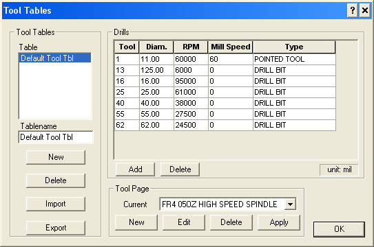
| 9. | Set the tool table | |||
Bring up the Tool Table
by selecting View->Tool Table
from the menu bar or by clicking on the Tool Table button
( ).
There should be an entry for each diameter of drill that you have used
and an entry (with diameter 11.00) for the milling cutter.
Change the type
of the milling cutter from
End Mill
to
Pointed Tool
by clicking on the entry in the
Type
field and selecting from the drop-down list. ).
There should be an entry for each diameter of drill that you have used
and an entry (with diameter 11.00) for the milling cutter.
Change the type
of the milling cutter from
End Mill
to
Pointed Tool
by clicking on the entry in the
Type
field and selecting from the drop-down list.
|
(Click to enlarge) | |||
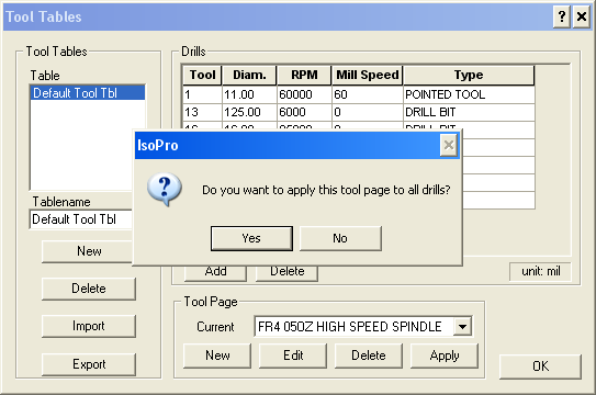
| Even though it already appears in the Tool Page block, explicitly choose and select FR4 05OZ HIGH SPEED SPINDLE from the Current field. Answer Yes when asked if you want to apply the page to all drills. |
(Click to enlarge) | |||
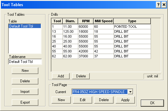
| When this is done, the entries in the RPM and Mill Speed columns should change. Finally click OK to close the table. |
(Click to enlarge) | |||
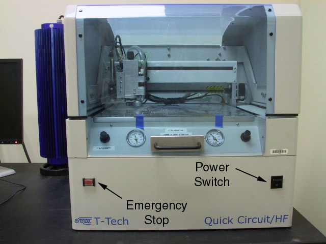
| 1. | Turn on | |||
|---|---|---|---|---|
The power switch is on the lower left front panel of the machine.
Before turning it on, examine the machine to verify that:
| ||||
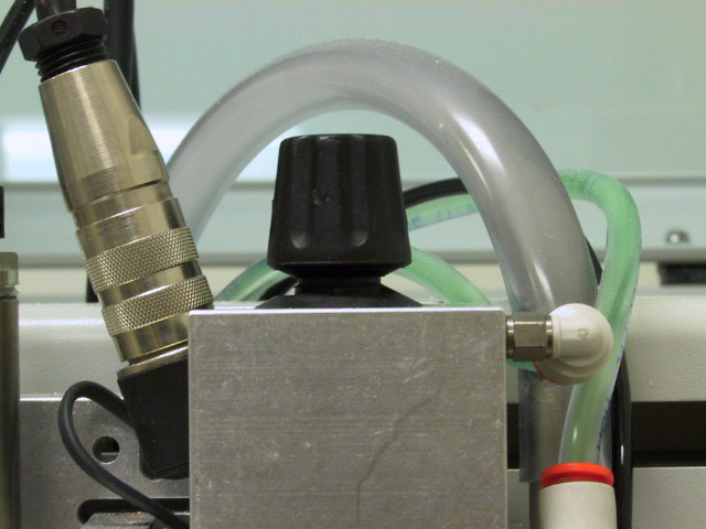
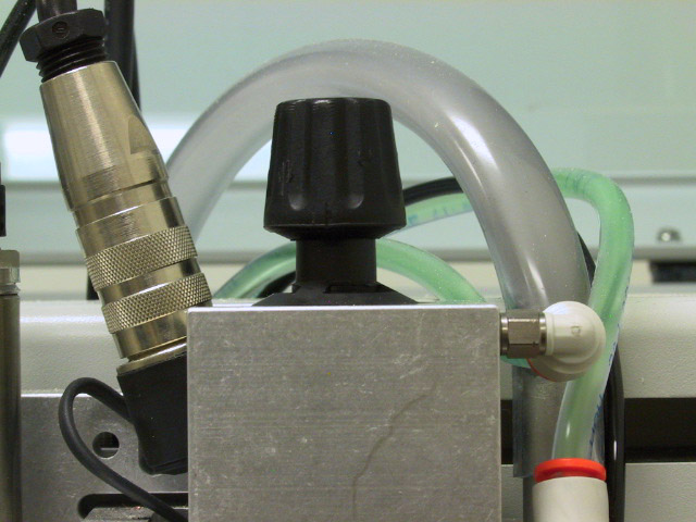
| After turning on the power, verify that there is coolant (a pale green fluid) present in the cooling hoses and that there are no bubbles in the lines. | ||||
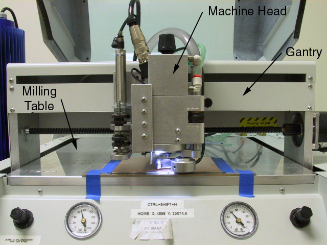
| Before proceeding, be sure you are familiar with the parts of the machine as described in the next two steps. |
(Click to enlarge) | |||
| 2. | The major parts | |||
(Click to enlarge) | ||||
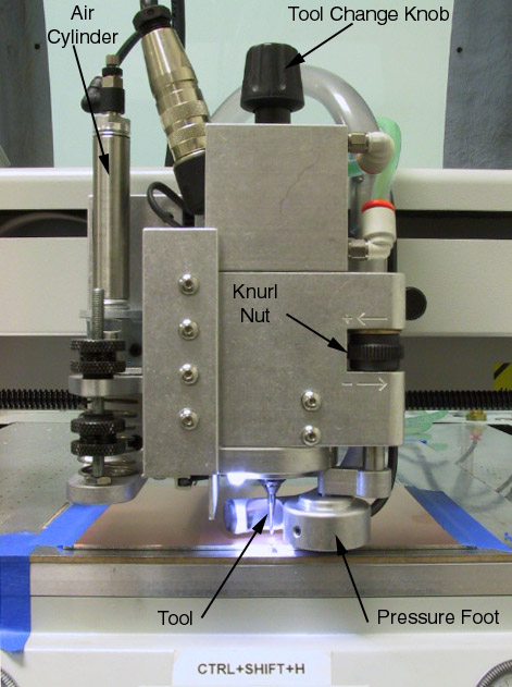
| 3. | The machine head | |||
(Click to enlarge) | ||||
| 4. | Initialize | |||
| Select Initialize from the Mill menu in IsoPro. The head will move slowly toward the left edge, then toward the front of the work area. Once the coordinate reference has been established, the head will move to the home position (0,0) at the front center. At this point, the machine is ready to use. | ||||
| 1. | Pin and tape the board | |||
|---|---|---|---|---|
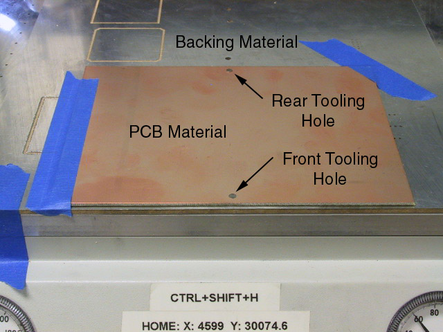
| Your blank board should have two 1/8 inch tooling holes, one in the center of the front edge, and one in the back. The backing material has two holes in the same locations, each of which should have a dowel pin in it. If either of the pins is missing, get one from the black plastic box next to the machine and place it in the hole. Place the holes in your board over the pins and press down until the board is seated firmly against the backing material. There should be no gap between the bottom of the board and the top of the backing material. If there is, check to see that the board is not warped and that there are no burrs on the surface of the backing material. If the board is warped, replace it with another. If there are burrs, remove them. The top of the front dowel pin should be below the surface of the PCB material. If it is above the surface of the board, DO NOT PROCEED, or you will damage the pressure foot. |
(Click to enlarge) | |||
| Tape the left and back edges of the board to the backing material. Do not tape the bottom of the board, except at the leftmost edge. If you tape the right hand edge, the tape must overlap the edge of the board by no more than 1/8 inch. Otherwise the pressure foot will ride on the tape, giving an incorrect depth of cut. |
(Click to enlarge) |
|
|
| 2. | Set the tool height for drilling | |||
|---|---|---|---|---|
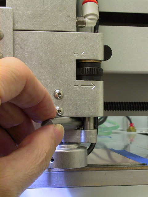
| Select Machine->Home from the menu bar. This will bring the machine head to the front of the table for convenient access. Adjust the knurl nut on the right hand side of the machine head until the smaller of the two gage pins (0.270) bottom of the machine head and the top of the pressure foot arm. |
(Click to enlarge) | |||
| Do not attempt to adjust any of the knurled knobs on the left hand side of the machine head or on the air cylinder. Having these improperly set can result in a defective board, broken tools, or damage to the machine. | ||||
| 3. | Run the drill layer | |||
| The standard drill kit contains 6 drills: 16 mil, 20 mil, 25 mil, 30 mil, 36 mil, and 40 mil. Holes larger than 40 mils will be cut by a contour router. This means we will have to change tools several times during the drill pass. | ||||
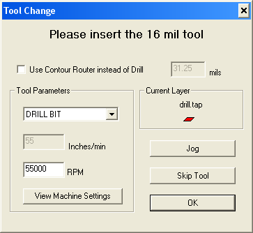
| Select Mill-Run Layer from the menu bar. Select holes.drl from the list and click OK. The machine head will move to the tool change position and you will get a dialog box asking you to install the first drill. If you have used the nc_tools.txt file included in the pcb.zip file, your drills should be sorted in ascending order and the first drill will be 16 mils. If your first drill is greater than 40 mils, click Skip Tool until you get a drill 40 mils or less. |
(Click to enlarge) | |||
| 4. | Install the first tool | |||
| Lock the spindle by pressing down on the tool change knob. If there is a tool in the spindle, rotate the knob counter clockwise until the collet is loosened, carefully remove the tool, and place it in its appropriate container. |
(Click to enlarge) | |||
| Insert a drill of the appropriate size and press carefully on the tip of the drill until it is seated firmly into the collet. |
(Click to enlarge) | |||
| While continuing to apply pressure to the drill, tighten the tool change knob until it is snug, but do not over tighten. Unlock the spindle by pulling up on the tool change knob. | ||||
(Click to enlarge) | ||||
|
|
| 5. | Drill the small holes | |||
|---|---|---|---|---|
| Before clicking OK on the Tool Change dialog, verify that the spindle is unlocked (i.e. the tool change knob is up). Click OK on the tool change dialog. The spindle and vacuum will start and the machine head will move to the position of the first hole. After a brief wait for everything to come up to speed, the head will lower, pause briefly, raise, move to the next hole position, and repeat until all of the 16 mil holes are drilled. (If you are using one of the standard frames, this will take a while, as there are a large number of separation holes.) After the last hole of the current size has been drilled, the spindle and vacuum will stop, the head will move to the tool change position, and you will be asked to install the next drill. | ||||
| If your drills are sorted, continue to change drills until asked for the first size over 40 mils, then go to the next step. If your drills are not sorted, click Skip Tool for any drill over 40 mils, then rerun the drill layer to drill the large holes as explained in the next step. | ||||
| 6. | Drill the large holes | |||
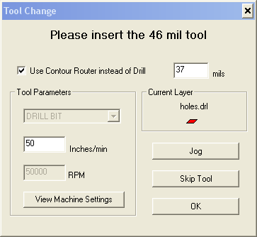
| To avoid having to stock a large number of drills, all holes larger than 40 mils are cut with a single tool: a 1 mm (39 mil) contour mill. When asked to insert the first drill larger than 40 mils, insert the 39 mil contour mill and check the box marked Use contour mill instead of drill. There's a bug in the T-Tech software which causes it to cut undersize when contour milling. If you specify the correct size (39 mils) for the contour mill, your holes will be too small. If you specify a size of 37 mils, the holes will be roughly the correct size. Set the Inches/min field to 18. Otherwise the tool is likely to break on large diameter holes. |
(Click to enlarge) | |||
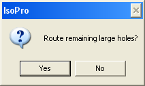
| When asked if you want to cut all remaining large holes with the contour mill, answer YES. |
(Click to enlarge) | |||
|
|
| 7. | Discard dull tools | |||
|---|---|---|---|---|
| The contour mill wears fairly quickly, and when it is dull it is likely to stall, and if it stalls it will almost certainly break. One way to tell if your contour mill is too dull is to wait for it to break. The best way is to examine it carefully after each use (use the microscope on the solder bench) and discard it when it shows significant signs of wear. Another is to simply replace it regularly: 10 boards is about the maximum life you should expect. | ||||
| The regular drills also wear out and will break when dull. They don't wear quite as quickly as the contour mill, so you should get more than 10 boards without trouble. However, unless you are visually checking for wear, it would be a good idea to replace them at the 10 board mark as well. | ||||
| 8. | Insert the milling tool | |||
| Move the machine head to the Tool Change position and insert a EM2E8-0625-90V milling cutter. Before returning the machine head to the Home position, wipe the bottom of the pressure foot with your finger tip to remove any accumulated debris. | ||||
| 9. | Set tool height for isolation milling | |||
| This is the most complicated step in the entire process. However, it is necessary that it be performed correctly or your board will be unusable. If the tool is too high, isolation will be incomplete and traces will be shorted together. If it is too low, the isolation cut will be too wide, which will destroy narrow traces and pads with small annular rings. | ||||
| Select Mill->Tool Change from the menu. Place an EM2E8-0625-90V milling cutter into the spindle, tighten the collet, and release the spindle lock (pull the tool change knob up). Set the approximate tool height using the same procedure as for setting the drill height, but use the larger of the two gage pins (0.287). |
(Click to enlarge) | |||
Because of variations in tool length, changes in length as the tool wears,
and changes in the height of the pressure pad as it wears, the gage pin
can only get us
close
to the correct height.
To get the correct tool height, we will now refine our approximate height
using the following procedure.
| ||||
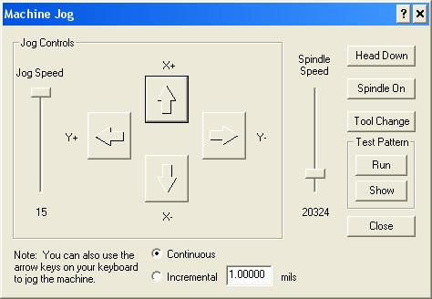
| Bring up the Jog panel (Mill->Jog). |
(Click to enlarge) | |||
| Using the X+ button, move the machine head to an unused area at the rear of the board. |
(Click to enlarge) | |||
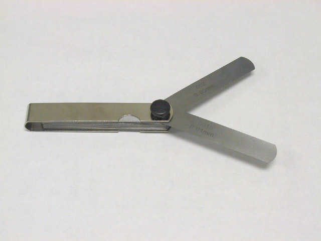
| Select a feeler gage blade in the range of 0.002" to 0.006". |
(Click to enlarge) | |||
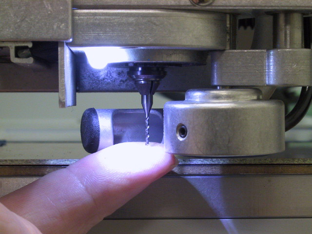
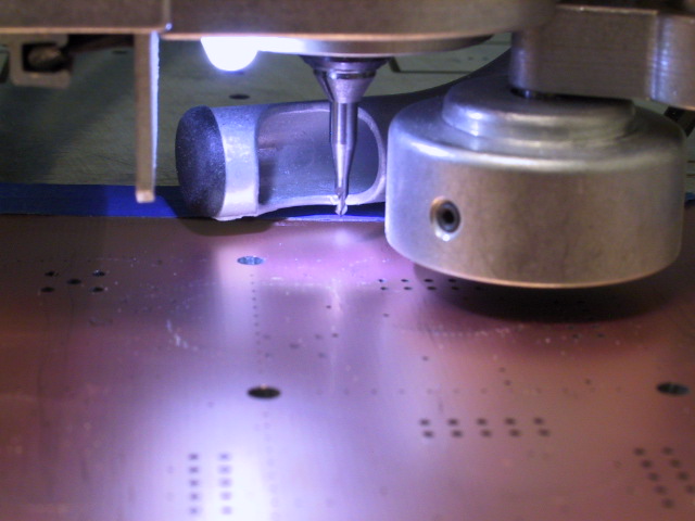
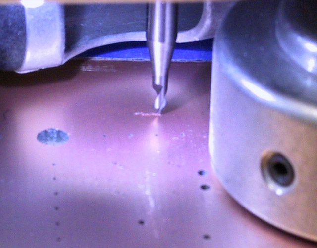
| Click on the Head Down button. Gently attempt to slide the blade beneath the tip of the tool. If it won't fit, as shown in the photo, the distance between the tool and the board is less than the thickness of the blade. Select a thinner blade and try again. |
(Click to enlarge) | |||
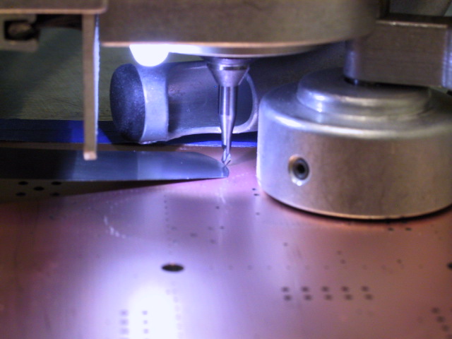
| If the blade slides easily beneath the tool, the distance between the tool and the board is more than the thickness of the blade. Select a thicker blade and try again. |
(Click to enlarge) | |||
| Continue this process until you find the thickest blade which will pass under the tip of the tool. This is the spacing between the tool and the board. Divide this distance by 0.0004" (the size of one click of the height adjustment knob). This is the number of clicks by which we need to lower the tool to just touch the surface of the board. Raise the head (by clicking on the Head Up button) and turn the knurl nut in the "+" direction by the number of clicks calculated above. | ||||
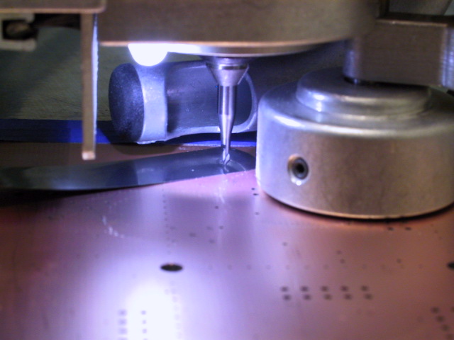
| Click the Spindle On button and set the spindle speed to about 25,000 rpm. If this is the first time you have started the spindle from the job panel, the motor will accelerate to maximum speed (100,000 rpm) regardless of the speed indicated on the slider. You must grab the slider and change the setting before it will take effect. Click the Head Down button, jog about 1/8" to the right, and click the Head Up button. There should be a faint mark on the copper surface along the path where the tool traveled, as shown in the picture on the right. If not, adjust the tool by one click in the "+" direction and repeat the Down, Jog, Up process until the tool just leaves a visible scratch. If the scratch is very deep, adjust the tool by one click in the "-" direction and repeat until it disappears, then lower by one click. At this point the tool is barely in contact with the surface. |
(Click to enlarge) | |||
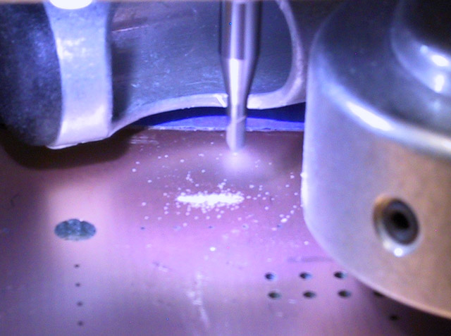
| Lower the tool by 10 clicks. Repeat the Down, Jog, Up process once more. You should see a cut which looks like the one in the picture on the right. The small track of yellow powder along the sides of the cut is an indication that the tool has penetrated to a sufficient depth below the lower surface of the copper and into the fiberglass substrate of the PC board. |
(Click to enlarge) | |||
| Turn off the spindle, and move the machine head away from the cut, either with the jog panel, or by selecting Material Change from the menu. Brush the dust away from the cut and carefully examine it to insure that it has completely penetrated the copper and there is adequate space between the two edges. | ||||
| 10. | Run the top layer | |||
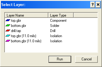
| Select Mill->Run Layer from the menu bar. Select the layer named "top.gbr (11.0 mils)" of type "isolation" from the table. Click the RUN button. |
(Click to enlarge) | |||
| Monitor the run to insure that it continues to cut to the proper depth. If the board is warped, or there is a burr between the board and the backing material, the depth of cut will be uneven, leading to incomplete isolation. A consistent track of yellow powder on the sides of the cut is an indication that things are going well. Its absence is an indication that the mill is no longer penetrating the copper layer. If this happens, stop the run, correct the problem, and restart. If necessary, lower the tool by two clicks. | ||||
| 11. | Turn the board over | |||
| When the top layer isolation is complete, the spindle and vacuum will turn off and the machine head will return to the home position. Select Mill->Material Change from the menu bar. Untape the board and rotate it 180° about the axis formed by the two tooling holes. This will put what was the bottom of the board on top, with what was the front of the board still at the front. Retape the board, and click Return to previous position on the Material Change dialog. | ||||
| 12. | Run the bottom layer | |||
| If there is any doubt in your mind that you remembered to set the type of the bottom layer to Solder, now is the time to resolve it. If the back of the board is not mirrored, the cuts will be in the wrong place. | ||||
| Select Mill->Run Layer from the menu bar. Select the layer named "bottom.gbr (11.0 mils)" of type "isolation" from the table. Click OK. Watch the first few cuts to insure that they are in the right place and still of the correct depth. | ||||
| When the run is complete, select Mill->Material Change from the menu bar. | ||||
| 13. | Inspect board | |||
| Carefully examine your board to insure that all isolations have cut completely through the copper and into the underlying substrate. Make sure that all holes that are supposed to be in your board have actually been drilled. Check all corners for copper slivers, as described in the instructions on soldering milled boards. | ||||
| Because the tooling holes precisely define the position of the board on the milling table, you can remove and replace it and the milling tool or drill will be able to return to exactly the same place. This means that if you find a mistake before you cut out your board, you can fix it by putting the board back in the machine and recutting or redrilling the problem area. | ||||
| 14. | Turn things off | |||
| Remove the tool from the spindle and return it to its proper container. Turn off the T-Tech machine and close the cover. If you are using a flash drive to store your board files, remember to remove it. | ||||
| 15. | Discard dull tools | |||
| Just like the other tools, the isolation milling cutter wears and will eventually fail. However, rather than abruptly breaking, it gives clearer advance notice of its wear: a dull cutter will produce a ridge of burrs on either side of the cut. When this happens, remove the burrs, discard the cutter, and replace it with a sharp one. Since removing the burrs is a tedious process, you should visually inspect your cutter after each use and replace it when it shows signs of excessive wear. | ||||
| 16. | Separate the boards | |||
| Separate your boards (or board) by cutting along the lines of 16 mil holes with the the shear. If you are very careful, you can line the board up by eye, but a much more accurate way is to place two pieces of 28 or 30 ga wire in the furthest separated holes of a row and use them as guides to align the row with the edge of the lower blade of the shear. | ||||