Boolean Unit Subcomponents
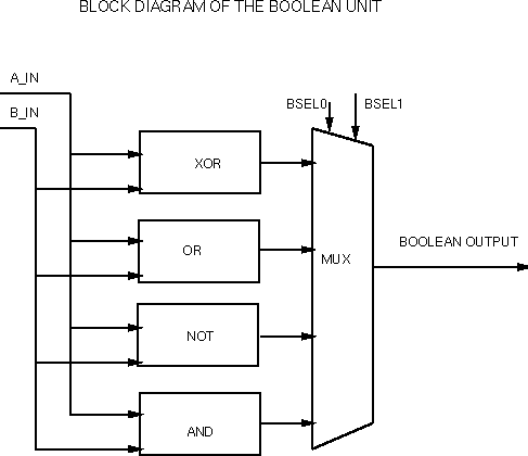
The design of the boolean unit is very simple, using only basic
gates stacked in eight-bit patterns. The basic scheme follows the below
block diagram.

The select inputs to the multiplexer are the low-order bits of the
opcode. These bits select as follows:
| OP1 | OP0 | Function |
|---|
| 0 | 0 | AND(A,B) |
| 0 | 1 | NOT(A) |
| 1 | 0 | OR(A,B) |
| 1 | 1 | XOR(A,B) |
In order to minimize the amount of routing needed, this multiplexer is
distributed across the AND, OR, NOT, and XOR subcells. Each
8-bit logic block is followed by an 8-bit transmission gate, controlled
by a single select input. A separate logic unit generates these four
select inputs: AND_SEL, OR_SEL, NOT_SEL, and XOR_SEL. The logic for this
unit consists of four NORs that effectively perform a 2-4 decode of the
low-order opcode bits.

