PLA
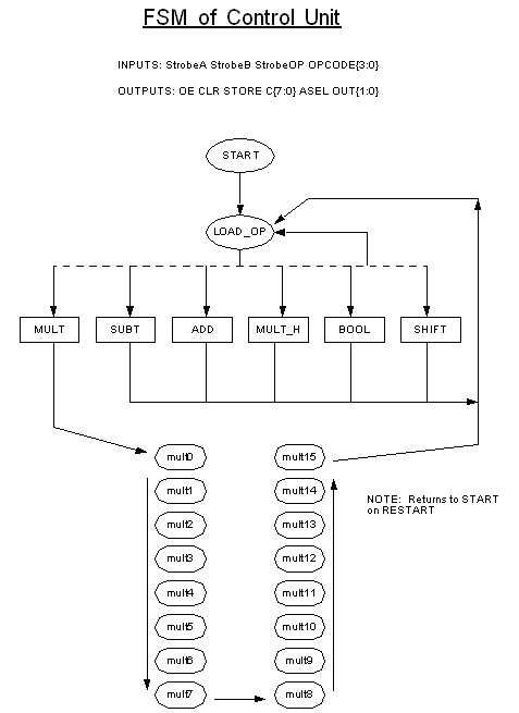
We use a PLA to implement our Control unit. The PLA follows this state
diagram:
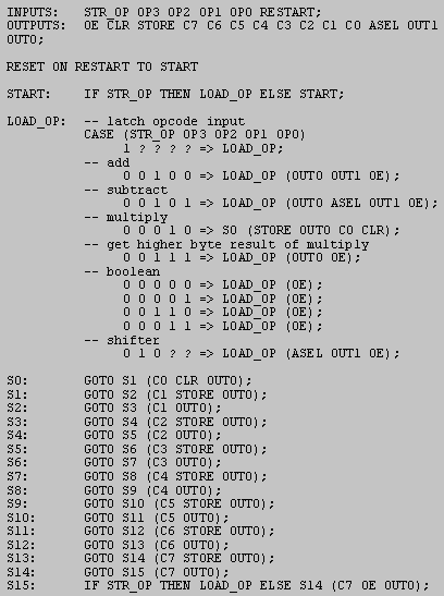
 The "meg" file that expresses this state diagram is:
 On RESET signal going HIGH the Control Unit (CU) goes to state0. It remain=
s in
state0 until STR_OP goes HIGH. On STR_OP going HIGH the CU goes to state1.=
The
STR_OP signal comes from the user and the user should make sure that the
OP_CODE is active and stable before pulling the STR_OP signal LOW (for val=
id
opcodes please refer to The functional description). Now the CU passes control signals to=
all
the units (Boolean, Multiply, Shift and Adder) and waits for one clock cyc=
le
before pulling the OE signal HIGH (except for the MULTIPLY operation). The=
user
is expected to continuously poll the OE pin before reading the outputs. On=
OE
signal going HIGH the user is assured that the outputs are stable. For the=
next
operation, the STR_OP signal should again be pulled up before placing the =
new
opcode. It should be noted that all the operations of the ALU except for t=
he
MULTIPLY takes one clock cycle. For the MULTIPLY operation the OE signal i=
s
asserted after 16 cycles.


