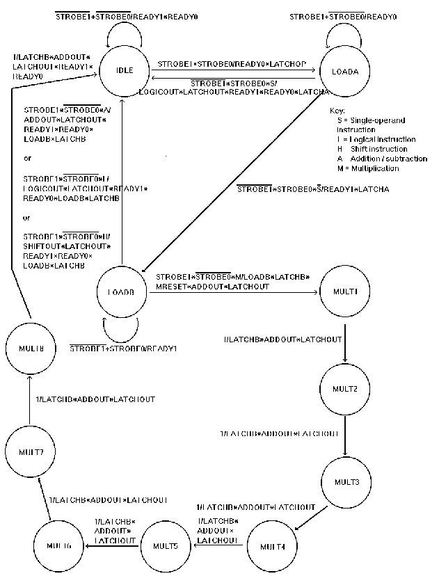
Finite State Machine Model of the ALU Control Logic
The high-level state machine of the ALU is straightforward and
simple. Many related states can be collapsed, letting simple control
logic, based on the unique opcodes, run the finer details of each
operation. For example, all two-operand operations other than
multiplication follow the same path through the ALU. Various control
signals must be asserted along the way during state transitions to guide
the particular operations.
Originally, we intended for the control logic to have one READY signal,
which it would assert when it was ready for a new opcode. If it saw an
opcode that it did not recognize, it would assert an ERROR signal and
continue to wait for a valid opcode. Otherwise, it would latch A on the
next cycle and B on the cycle after that. After some consideration, it was
decided that while this might be a most efficient implementation in an
integrated environment where all the subsystems are working together
perfectly, it might make testing and debugging on a workbench difficult.
We decided to use pairs of READY signals and STROBE to make it possible to
slow down the effective operation of the chip without slowing down the clock.
On each cycle where the ALU is waiting for an input, the control logic will
present a prompt through the two READY signals. It will wait until it sees
the appropriate response on the STROBE signals, and then it will latch the
input on the next cycle. The table below shows the prompts and expected
responses for each input.
| input |
READY1.READY0 prompt |
STROBE1.STROBE0 response |
| opcode |
11 |
11 |
| A |
01 |
01 |
| B |
10 |
10 |
-
idle
Hold the READY flags high while waiting for both STROBE signals to be
asserted. Latch the opcode and assert READY0 on the transition to
loada.
-
loada
Hold READY0 high until STROBE0 is asserted and STROBE1 is deasserted.
Then...
-
If the opcode is unrecognized, go back to idle, asserting the
ERROR signal and both READY signals.
-
If the opcode is for a single-operand operation, go back to idle,
asserting the appropriate control signals on the way to latch A, guide the
operation, and latch the output.
-
If the opcode is for a two-operand operation, go to loadb, latching
A and asserting READY1 on the transition.
-
loadb
Hold READY1 high until STROBE1 is asserted and STROBE0 is deasserted.
Then...
-
For multiplication, we will enter the shift-and-add routine
(mult1), latching B and asserting control signals (MRESET, ADDOUT,
and LATCHOUT) on the transition.
-
Otherwise, go to idle, asserting the appropriate control signals on
the way to latch B, guide the operation, and latch the output.
-
mult1-mult8
Placeholder states as the shift-and-add multiplier runs its course. ADDOUT
is asserted to let the adder drive the output bus. LATCHB and LATCHOUT are
held high to enable the self-shifting registers. From the last state, we
go to idle, latching the output and asserting the READY signals
along the way.
Each row in the table represents a particular operation's transitions
through the ALU, ignoring any polling loops. The column represents the
current state and the cell represents the next state. All operations are
assumed to start in state idle. For example, an addition
operation starts in state idle, moves to state loada, then
loadb, then back to idle. If it is ever in
any other state, a significant error has occurred.
State transition table
|
idle |
loada |
loadb |
mult1 |
mult2 |
mult3 |
mult4 |
mult5 |
mult6 |
mult7 |
mult8 |
| single-operand |
loada |
idle |
| multiply |
loada |
loadb |
mult1 |
mult2 |
mult3 |
mult4 |
mult5 |
mult6 |
mult7 |
mult8 |
idle |
| other double-operand |
loada |
loadb |
idle |
| unknown opcode |
loada |
idle |
State transition diagram
The control logic of the ALU is implemented using a script called
platool to build a magic file from a text file
(called a meg file). The meg file contains a description of the finite
state machine that should be implemented by the resulting PLA. Our
meg file implements the finite state machine
described above.
-
Initial functional design: Doherty, Morse, Pritchard
-
State transition diagram: Doherty
-
Primary meg file development/debug: Pritchard
-
Meg file debug: Doherty, Morse, Pritchard
-
Functional simulation: Doherty
-
Webpage text/HTML: Pritchard