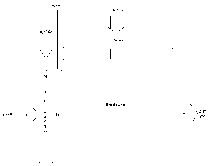
The shifter is very simple. It's job is to perform the different shift operations on the A input value. The number is shifted by the number of places equivalent to the lower 3 bits of the B input, namely B[2:0].
The shifter is basically a standard barrel shifter block with input control logic. The 3:8 decoder determines which select line to assert to the barrel shifter. Also, due to the nature of right and left shifting, op2, which specifies either a left or a right shift must reverse the select lines when op2 is high. (i.e. SEL[x] = SEL[7-x])
The changing requirements of the different shift operations also forced some heavy input logic to be employed between the pure A bus and the input to the barrel shifter. The lower three bits of the op-code control this logic.

The following is a table of the outputs of the A-control logic for the different possible opcodes.
| op[2:0] | operation | control logic output [14:0] |
|---|---|---|
| 000 | Logical Right Shift | GND*7,A[7:0] |
| 001 | Arithmetic Right Shift | A[7]*7,A[7:0] |
| 010 | Right Rotate | A[6:0],A[7:0] |
| 100 | Logical Left Shift | A[7:0],GND*7 |
| 110 | Left Rotate | A[7:0],A[7:1] |
From the above table, it is easy to see why the select lines must be reversed when performing left, instead of right, shift.
The correct answer now plops out of the shifter.
An irsim command file was used to simulate the five operations of the shifter: