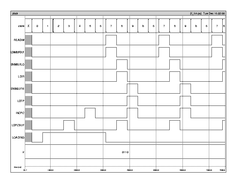
Command File
| check Instruction Fetch
clock clka 0 1 0 0
clock clkabar 1 0 1 1
clock clkb 0 0 0 1
clock clkbbar 1 1 1 0
vector ir ir3 ir2 ir1 ir0
vector state s1 s2 s3 s4
ana state readim ldimbufout enimbuflo ldir enimbufhi ldtp incpc ldpcbuf loading ir
V RESTART 1 0 0 0 0 0 0 0 0 0 0 0 0 0 0 0 0 0 0
V LOADDONE 1
V ENTER 1
V ir 0110
V DMSEG 0
V IMSEG 0
V IR3 0
V IR2 1
V IR1 1
V IR0 0
R
Simulation

Notice:
- First (cycle 7) an IM location is loaded into the buffer register
(READIM and LDIMBUFOUT)
- Then the low bits (opcode) are loaded into the IR register (ENIMBUFLO
and LDIR)
- Then the high bits (operand) are loaded into the TP register (ENIMBUFHI
and LDTP)
- After the IM is accessed, the PC is incremented (INCPC)
- At least one cycle before INCPC, LDPCBUF loads the buffer with the
current PC value to calculate the next PC address
- This cycle is successfully repeated for the next instructions
