Final Testing Report
Final Presentation
Omnilab Setup
We tested our chips using an Orion Omnilab test station connected to an IBM
PC. We used the standard setup utilizing stimulus banks one and two, and
analyzer banks A through D. We triggered the tests off of the init
signal. The only difficulty that we discovered in setting up for the tests
was that we used an old version of our CIF file when wiring and
accidentally wired the chip upside down.
Test Vectors
We were able to test each of the logical functions completely since each
bit is independent and hence only a total of four transitions had to be
checked. (1->0, 1->1, 0->1, 0->0) We did not attempt to exhaustively test
the adder and square root components since there were so many
possibilities. We tested the adder for overflow, each bit for stuck at 0
and stuck at 1, and a few random test cases. We tested the square root
with its maximum and minimum values, a negative number, and some more
random cases.
Functionality
All 5 chips passed the static tests with a minimum resistance between
Vdd and GND of 15 MOhms, and negligible resistance
between the three Vdds, as well as the three
GNDs.
After running our test vectors we discovered that the Load, And, Or, Not,
and Adder functions worked correctly, but the square root failed. On
reexamination of the magic files we discovered that when the square root
was integrated into the main design the clocking scheme was inadvertantly
changed. When IRSIM testing was done with the integrated chip, the square
root was not exhaustively tested again, and for the test cases chosen the
square root still worked.
IRSIM vs Omnilab
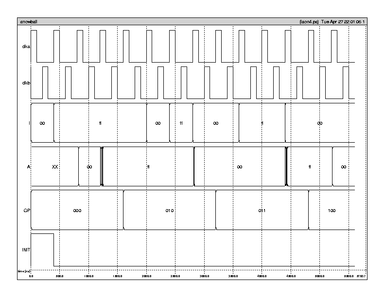
IRSIM results for the load and logical functions complete
test vector
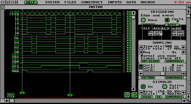
Omnilab results for the load and logical functions complete
test vector
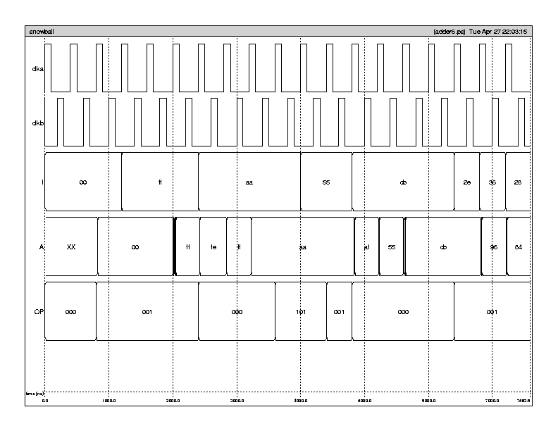
IRSIM results for the adder
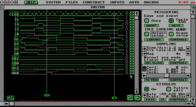
Omnilab results for the adder
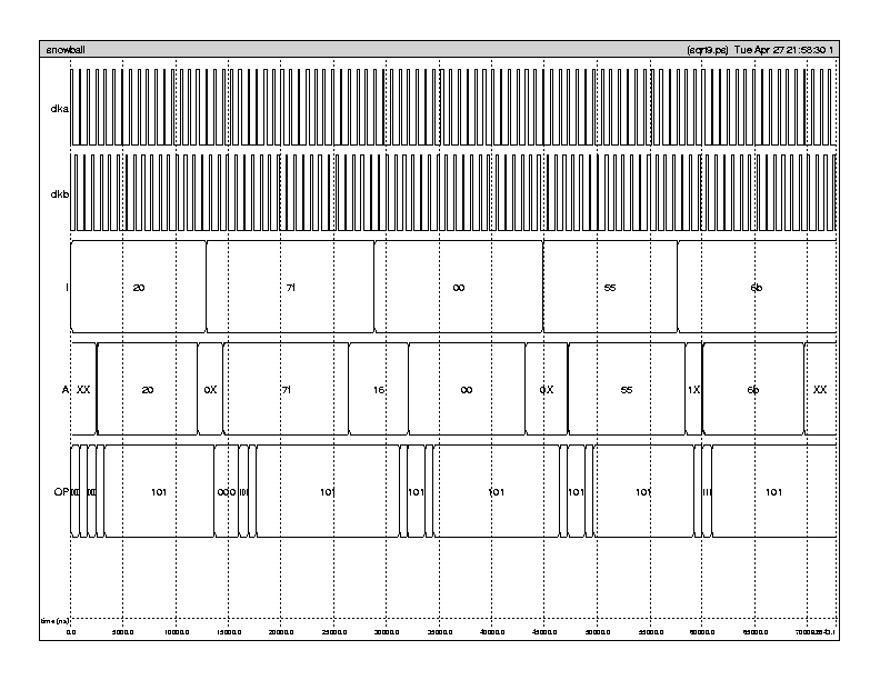
IRSIM results for square root
Omnilab results for square root
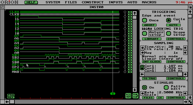
As stated above it can be observed that the IRSIM and Omnilab results
for the logical functions and adder are the same, while the square root
performs differently.
Speed response
The speed response of the chip was limited by the single cycle adder.
Spice analysis estimated that the maximum clock frequency of the chip would
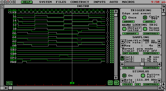
be 16 MHz. When we tested the chip we found that the adder functioned
correctly at 6.8MHz, but failed at 17MHz. Limitations of the test
equipment prevented us from obtaining a more precise estimate of the clock
speed. However these results agree with those obtained in Spice.
Adder failing at 17MHz
The logical section of the chip was capable of running at 17MHz, but failed
at 34MHz.
Logical functions failing at 34Mhz
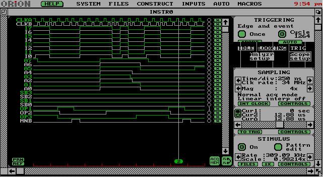
The Omnilab outputs failed severely enough that it is not even possible to
isolate the instance where the circuit fails.
Problems or suggestions
The equipment in lab was severely dated. The PC's had problems printing
and one didn't have a working cache. When a file was updated on the Unix
machines Omnilab could not read the new file, and had to be exited and
restarted unless the file was renamed.
MOSIS Report
A text copy of our MOSIS report can be found here.
Last modified: Mon May 3 15:10:28 CDT 1999


