Final Report
Omnilab Setup
We used the standard Omnilab setup to test Bob. This includes the Omnilab
workstation and corresponding pc. This is connected to our chip via a
breadboard. Since our chip did not incorporate any peripherals
(e.g. memory, A/D converter, etc.), there was no real customization
required here.
Test Strategy
We converted several of our original Irsim test vectors to a format
compatible with Omnilab. These included simple additions, subtractions,
multiplications and divisions.
All of our tests failed on all of our chips. No matter what we provided
as inputs to the chip, all the outputs remained low. This is a
particularly strange result because the testing hardware defaults to high.
This suggests that either a signal is getting through, forcing the output
low or the output pins are somehow grounded. In the original Magic design,
neither of these appear to be the case, however. Apon re-simulating the
chip, we do not find any behavior to suggest the Omnilab problems we
observe.
Test Results
Initial Power and Ground Testing
| CHIP # |
Avg. Vdd-Vdd |
Avg. GND-GND |
GND-Vdd |
Vdd-GND |
| 1 |
2.6 Ohms |
2.5 Ohms |
3.12 MOhms |
7.87 MOhms |
| 2 |
2.5 Ohms |
2.1 Ohms |
3.12 MOhms |
7.92 MOhms |
| 3 |
2.6 Ohms |
2.1 Ohms |
3.14 MOhms |
7.91 MOhms |
| 4 |
2.4 Ohms |
2.0 Ohms |
3.14 MOhms |
8.06 MOhms |
| 5 |
2.5 Ohms |
2.1 Ohms |
3.14 MOhms |
7.82 MOhms |
Irsim Vector Output
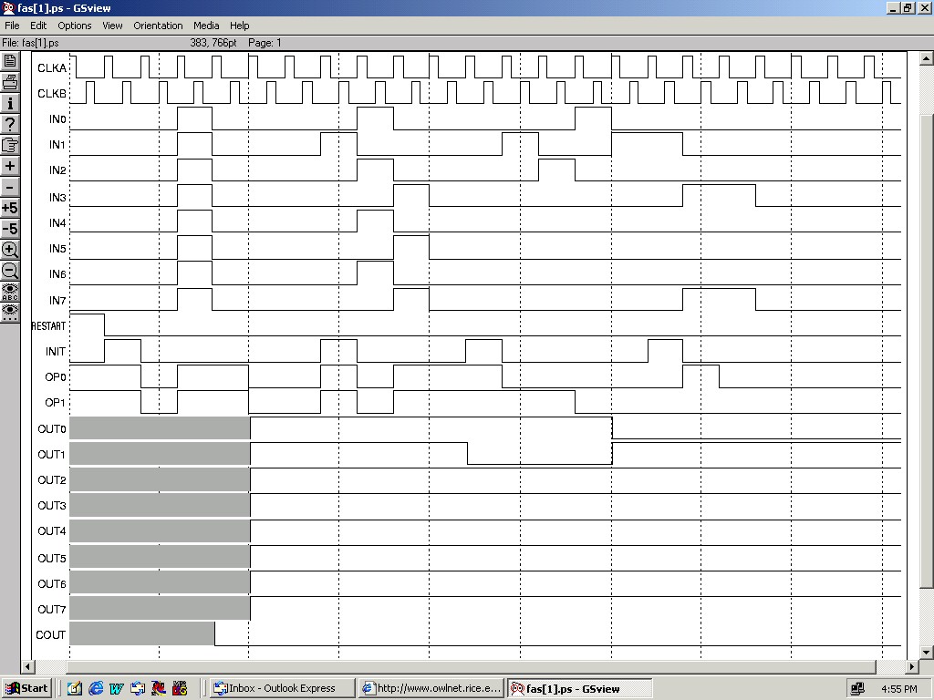
The above image shows a working simulation of both addition and subtraction.
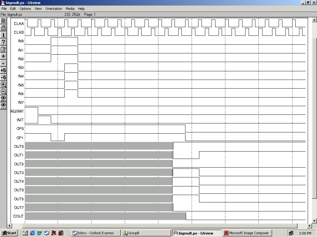
The above image shows a working simulation of multiplication.
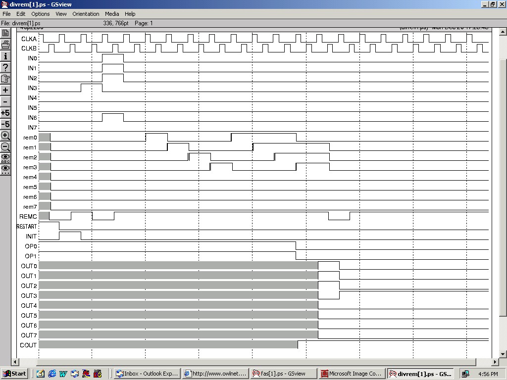
The above image shows a working simulation of division with remainder.
Omnilab Test Results
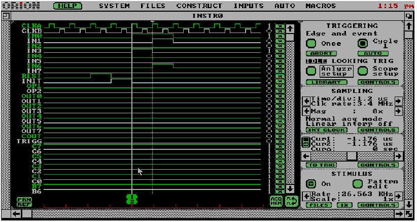
This is the failed test of the manufactured chip. Notice that all the
outputs are low. This should not be.
Possible Reasons for Failure
We have been unable to determine the exact reaons for our chip's
failure. Since our simulation still appears to work with our final Magic
file, we are left without anything definite. We have, however, come up
with a few hypotheses.
- Missing Substrate Contacts
- We were missing a few substrate conatacts in the original design.
However, if this was the problem, it should manifest itself in latch-up
which would produce excessive heat. The chip never showed signs of getting
hot.
- I/O Pad Enables Left Floating
- The unused I/O pads did not have their enables tied to either Vdd or
ground. When we tested the voltage of a pad with floating enable which was
directly adjacent to an input pad, we observed some ringing which appeared
to have the same overall shape as the input voltage asserted on the
adjacent pad. This suggests some leakage across the pads.
- Power and/or Ground Not Fully Connected in Core
- Since Irsim will merge the Vdd and GND automatically, even if they are
not fully connected, and the fact that our chip did not appear to produce
any heat when connected to the simulator, we thought this could have been a
problem. Reverting to the Magic layout, and highlighting the Vdd and GND
nodes, we did not observe any unconnected nodes. We also examined several
of the major sections of the layout and found power and ground to be
connected to these. Finally, Irsim did not throw a warning about merging
Vdd or GND which it is supposed to when it merges nodes.
- Unconnected Nodes Within the Core
- Since Irsim will sometimes merge nodes within a layout, this is a
possibility. Also, another project experienced problems which they
attributed directly to this. In particular, they found that Irsim merged
nodes from different layers of the layout without displaying a warning
message. This remains a possibility with uur project despite the fact that
we did not find any instances of this on the final Magic layout. All it
might take is one unconnected control signal or clock to the right place to
cause the failure of the entire chip.