Wigner distribution
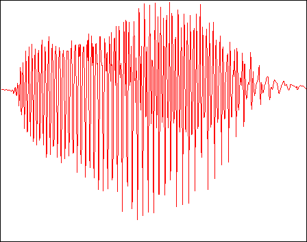
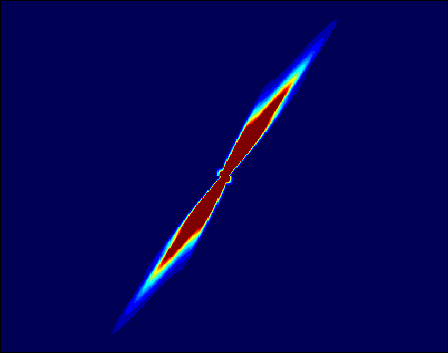
In some sense, the Wigner distribution (WD) is the 'fundamental' time-frequency representation (TFR), because it possesses a large number of desirable properties. Unfortunately, it also exhibits nonlinear artifacts called cross-components that can interfere with the true signal auto-components. To illustrate, we show below the bat echolocation chirp signal and its Wigner distribution
Bat chirp signal and its Wigner distribution
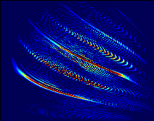
(In the above TFR image, time runs horizontally and frequency vertically, and the colors indicate the energy level. Click on any of these images to obtain a larger and higher resolution version.)
While the hyperbolic nature of the chirp is evident in the WD image, the copious cross-components would complicate a more detailed analysis. In general, WD cross-components have the following properties:
- A WD cross-component appears between each pair of WD auto-components.
- Each WD cross-component oscillates in time-frequency with a spatial frequency inversely proportional to the auto-component separation distance.
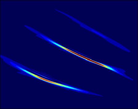
Ambiguity Function
The inverse Fourier transform of the Wigner distribution is called the (symmetric) ambiguity function (AF)
WD = Fourier transform{ AF }
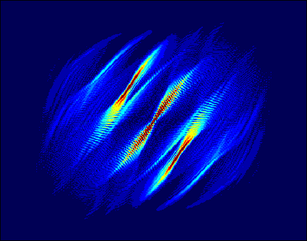
The AF of the bat chirp looks like this:
Ambiguity function of bat chirp
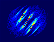
The Fourier transform maps the WD auto-components to a region centered on the origin of the AF plane, whereas it maps the oscillatory WD cross-components away from the origin. In the AF image above, the AF auto-components corresponding to the three harmonics of the bat chirp lie superimposed at the center of the AF image, while the AF cross-components lie to either side. The components slant in the AF because the bat signal is chirping.
Cohen's Class of TFRs
The fact that the auto- and cross-components are spatially separated in the AF domain means that if we apply a mask function to the AF, we can suppress some of the cross-components. This masking operation defines a new TFR
TFR = Fourier transform{ AF . Kernel }
with properties different from the WD. The mask function is called the kernel of the TFR. Since there are many possible 2-d kernel functions, there exist many different TFRs for the same signal. The class of all TFRs obtained in this fashion is called Cohen's class.
The WD is obviously a member of Cohen's class, with Kernel=1.
Spectrogram
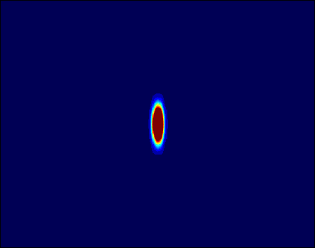
The spectrogram, the squared magnitude of the windowed short-time Fourier transform, also belongs to Cohen's class. Its kernel is the AF of the short-time window function. A typical spectrogram kernel looks like this:
Ambiguity Function and Spectrogram Kernel
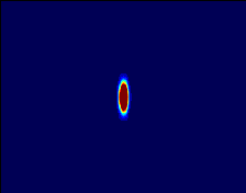
To obtain the spectrogram, we take the Fourier transform of the product of the above two images.
The poor concentration of the spectrogram can be blamed on the fact that the spectrogramSpectrogram Of Bat Chirp
kernel does not match the slanting AF auto-components of the bat chirp.
Since for any given signal some TFRs are `better than others,' kernel design has become an important research area. In order to find the `best' TFR for any given signal, our research focuses on optimization-based kernel design. Optimal-kernel TFRs adapt to the signal at hand in order to extract the maximum possible time-frequency information.
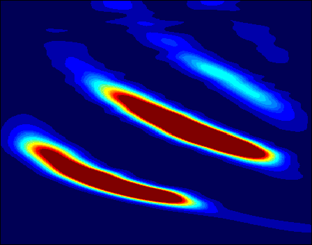
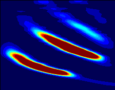
The optimal radially Gaussian kernel of the bat chirp is well matched to the AF auto-components
Ambiguity function and Optimal kernel
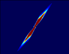
assign="justify">so a high resolution TFR results.
Research in Optimal-Kernel Time-Frequency Analysis at Rice
We have developed several different approaches to optimal-kernel time-frequency analysis, including:
- 1/0 Optimal-Kernel TFR
In this formulation, the optimal kernel turns out to have a special binary structure: it takes on only the values 1 and 0.
See: R. G. Baraniuk, D. L. Jones, A Signal-Dependent Time-Frequency Representation: Optimal Kernel Design, IEEE Transactions on Signal Processing, vol. 41, no. 4, pp. 1589-1602, April 1993. Abstract.
- Optimal Radially Gaussian Kernel TFR
We temper the `1/0 kernel' optimization formulation with an additional smoothness constraint that forces the optimal kernel to be Gaussian along radial profiles. In most cases, we prefer this TFR to the 1/0 optimal-kernel TFR. (This optimal-kernel TFR was illustrated above.) Matlab code is available for this TFR.
See: R. G. Baraniuk and D. L. Jones, Signal-Dependent Time-Frequency Analysis Using a Radially Gaussian Kernel, Signal Processing, vol. 32, no. 3, pp. 263-284, June 1993. Abstract.
- Adaptive Optimal-Kernel (AOK) TFR
Here, we adapt the radially Gaussian kernel over time to maximize performance. The resulting adaptive optimal-kernel (AOK) TFR is suitable for online operation with long signals whose time-frequency characteristics change over time. Matlab-compatible C code is available for this TFR.
See: D. L. Jones and R. G. Baraniuk, An Adaptive Optimal-Kernel Time-Frequency Representation, IEEE Transactions on Signal Processing, vol. 43, no. 11, pp. 2361-2371, October 1995. Abstract.
For further information on other optimal-kernel TFRs, please see our list of publications.