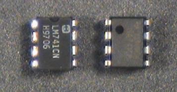
The 741 operational amplifier, or op-amp, comes in an 8-pin dual inline package (DIP) which looks like this
![\includegraphics[scale=0.640000]{opamps/cktsym.ps}](img173.png)
In order to function, the op-amp must be connected to an external power supply. Since we want to produce both positive and negative output voltages, we need both positive and negative voltages for the power supply. These are labeled \(V_\text{CC+}\) and \(V_\text{CC-}\) on the diagram. For a 741, the nominal values are \(V_\text{CC+}=15~\text{V}\) and \(V_\text{CC-}=-15~\text{V}\)
To avoid clutter, we won't show the power supply terminals (pins 4 and 7) on any of the subsequent circuit diagrams. However, they must be connected or your amplifier will not operate.
Note that there is no ground terminal on the op-amp. The zero reference point is established by the external circuit and is not important to the op-amp itself.
|
| ||
Step 1: |
If you have not already done so, wire the bus strips on
your breadboard to provide positive power, negative power
and ground buses.
Whatever color scheme you have chosen for your wires, you
should use the green binding post for ground, the black for -15 V,
and the red for +15 V.
| |
Step 2: |
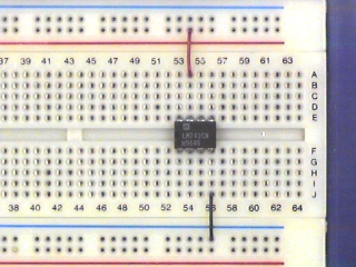
Plug an op-amp into the breadboard so that it straddles the gap
between the top and bottom sections of the socket strip.
If you have wired the power buses as suggested above, Pin 1 should
be to the left.
| |
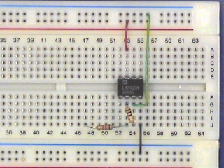
Step 3: |
Connect Pin 4 (\(V_\text{CC-}\)) to the negative power supply bus (-15 V).
Connect Pin 7 (\(V_\text{CC+}\)) to the positive power supply bus (+15 V).
| |
Step 4: |
Set up the +/- 25 power supply dongle. Turn on the power supply and set the VirtualBench voltage control
to 15 volts.
| |
Step 5: |
Turn off the supply and connect the supply to the breadboard with banana plug patch cables. Connect the -25V terminal to the black binding post on your breadboard, the +25V terminal to the red breadboard binding post, and the GROUND terminal to the green breadboard binding post. Note that none of the power supply output terminals are connected to ground. If we want the power supply zero volt reference connected to ground, we must make the connection ourselves. |
CautionThe moral: always wire your circuit with the power turned off and check your wiring carefully before turning the power on. | ||
Step 1: |
With the power turned off,
wire the following circuit.
Note that this is a 1000:1 voltage divider, so that a 1 V
signal at \(v_\text{in}\) results in a 1 mV signal at the input of
the op-amp.
![\includegraphics[scale=0.650000]{opamps/open_loop.ps}](img174.png)
| |
Step 2: |
Set the function generator to produce a 2 V p-p,
20 Hz sine wave.
| |
Step 3: |
Connect the function generator output to \(v_\text{in}\) of the circuit
above.
Connect
CH1
of the scope to \(v_\text{in}\) and
CH2
to \(v_\text{out}\).
Set the
CH2 VOLTS/DIV
to 5.
Make sure both channels of the scope are on
DC.
| |
Step 4: |
You should see a badly distorted
(clipped)
waveform at \(v_\text{out}\).
If you don't, try increasing the function generator output.
| |
Step 5: |
Adjust the square wave so that it is symmetric about the x-axis.
| |
Step 6: |
Note the positive and negative peak values of \(v_\text{out}\).
| |
Step 7: |
Connect a 100\(\Omega\) resistor from \(v_\text{out}\) to ground.
What happens to the output signal?
| |
Step 8: |
Remove the 100\(\Omega\) resistor from the op-amp output.
Set the function generator output to square wave.
Note the shape of the \(v_\text{out}\) waveform.
| |
Step 9: |
Make sure the DC offset control on the function
generator is set to zero.
| |
Remark: |
We have just seen a number of the shortcomings of a real (as opposed to an ideal) operational amplifier: clipping, which limits the maximum amplitude of the output; slew-rate limiting, which limits the maximum slope of the output; and offset, which gives a non-zero output for zero input. When we reduce the overall gain with feedback, some of these (e.g. offset) are reduced significantly, and we get an output which is a faithful reproduction of the input. However, other limits (such as maximum output level) must be respected for this fidelity to remain. |