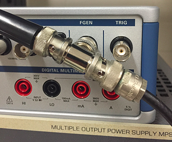
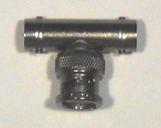
- Connect the BNC T-connector to CH1 of the scope.
- Use a BNC patch cord to connect one end of the T to the FGEN output. Connect a BNC clip lead to the other end of the T.
- Set the FGEN to produce a 2-V peak-to-peak, 100Hz sine wave.
- Set the DMM to AC Volts and connect the probes to the clip leads. What is the voltage reading on the DMM?
- Set the FGEN to produce a square wave. What is the voltage reading on the DMM?
- Reset the FGEN to sine wave. Note the reading on the DMM at 5 Hz, 50 Hz, 500 Hz, 5 kHz, and 50 kHz.
- What is the useful frequency range of the DMM for measuring AC signals?
o The AC voltage function of the DMM is calibrated to read (approximately) the RMS value of the waveform. RMS stands for root-mean-square i.e. the
square root of the mean value of the square of the function:
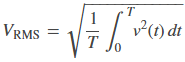
o We’ll see the importance of this when we study power. For now just remember that for a sine wave, VRMS = 0.707 Vpeak.
- Wire the following circuit using 10kΩ (brown-black-orange) resistors for both R1 and R2:
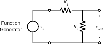
- What should the voltage divider ratio (vout/vs) be?
- Set the FGEN to produce a 2 V p-p sine wave.
- Measure vout with the oscilloscope. Is it what you expect? Why or why not?
- Change R1 and R2 to 47Ω (yellow-violet-black). What is the output voltage?
- Now change R1 and R2 to 1MΩ. What is the output voltage?
o Note: No circuit exists in isolation. To be useful its input or output (or both) should be connected to some other circuit. Unfortunately the interaction between the circuit and a non-ideal source or load causes it to behave differently than it would in an idealized situation. With careful design, this interaction can be minimized or accounted for. If ignored it can reduce the performance of the system, or keep it from working altogether.
- A potentiometer (pot for short) is a fixed value resistor with a third, movable contact or slider which may be positioned anywhere along the resistive element. If we represent the position of the slider by α, where α varies between 0 (fully counterclockwise) and 1 (fully clockwise), then the resistance between the lower end of the resistor and the slider will be αR and between the slider and the upper end will be (1-α)R, where R is the total resistance of the potentiometer.
- If we connect the two fixed contacts to a voltage source and measure the output between the movable contact and one fixed contact, we get a variable
voltage divider:
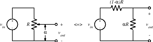
- Then the output is:
![]()
- Select a 10kΩ potentiometer. It will have three short wires sticking out in a triangular pattern. The center terminal is the slider contact and the two outer terminals
are the fixed contacts.
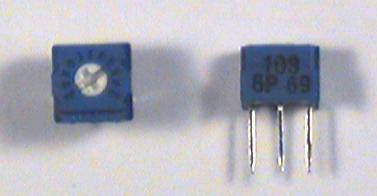
o Note: Figuring out the value of a pot can be tricky. Some pots are labeled directly with the value (e.g. "100" or "10K"). Others are labeled using the same code as for fixed resistors, except that numbers, rather than colors, are used. For example, a 10kΩ resistor would have the bands brown-black-orange. The values of these colors are 1, 0, and 3, so a 10kΩ pot would have the label "103".
- Wire the following circuit:
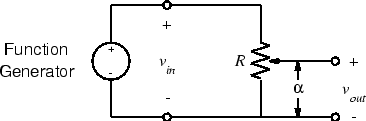
- Set the function generator to produce a 2 V p-p 100-Hz sine wave.
- Set the potentiometer adjustment screw to midscale and note down vout.
- The pot has a scale divided into 10 equal divisions, presumably representing 10 equal divisions of resistance. Set the pot to each of these 10 divisions and measure vout. Is this presumption correct?