Measuring the transfer function of an RC circuit is considerably more involved than measuring the attenuation of a resistive voltage divider. We have to make the measurement at a number of frequencies, and we must measure phase as well as amplitude.
- Select a 2.2 kΩ Resistor and a 0.33 µF capacitor.
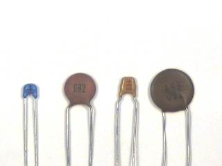
o Note: Ceramic capacitors use the same labeling codes as the potentiometers except that the units are picofarads (pF) instead of ohms. So a 0.33 µF capacitor would be a 330,000 pF capacitor which would have the code 334 (33×104).
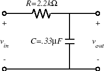
- Wire the following circuit:
- Connect the FGEN to supply vin and the oscilloscope to measure vout.
- Using the technique described in the Interlude, measure the frequency response of the circuit at the following frequencies: 20 Hz, 50 Hz, 100 Hz, 200 Hz, 500 Hz, 1 kHz, 2 kHz, 5 kHz, 10 kHz, and 20 kHz.
- Plot the magnitude of the transfer function vs. frequency on loglog axes and the phase on semilog axes. This can be done by hand or in Matlab.
- Using Matlab, compute and plot the expected transfer function for the circuit you built.How well does this compare with what you measured?