To use the antenna, hold it at arm's length, point it toward the transmitter, look through the clear plate at the rear of the telescope, and align the image of the LED with the center of the photodiode.
The first stage is a modified version of the circuit we used in Lab 4. The changes are:
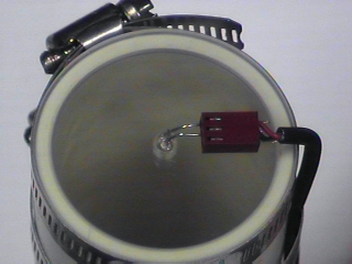
Also the photodiode is not mounted on the breadboard but is connected via a cable through the interface board. The diagram shows it wired to J1-5.
![\includegraphics[scale=0.600000]{ckt9.3.ps}](img197.png)
Plug the photodiode directly into the breadboard.
Connect the Scope to ![]() .
You should see a small DC voltage.
If you see a large DC voltage (about 15 V) check to be sure
the diode is connected with the correct polarity.
Verify that the voltage changes as you cover and uncover
the photodiode with your hand,
blocking and unblocking the light falling on it.
.
You should see a small DC voltage.
If you see a large DC voltage (about 15 V) check to be sure
the diode is connected with the correct polarity.
Verify that the voltage changes as you cover and uncover
the photodiode with your hand,
blocking and unblocking the light falling on it.
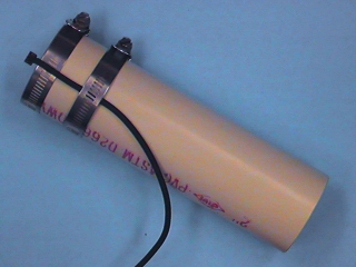
Unplug the diode from the breadboard and plug it into the connector on the receiver antenna (making sure to keep correct polarity. Plug the other connector into J1-5 of the interface board. Verify that that the circuit still responds as you point the antenna at various sources of light (and dark).
Because of the wide variation in the amplitude of the received signal, we need more gain and a volume control for the earphone amplifier.
![\includegraphics[scale=0.600000]{ckt9.5.ps}](img198.png)
Connect the output of the photodiode amplifier to the input of the earphone driver. Set the volume control to midscale. You should hear a buzzing sound. To make sure that this is optical and not electrical noise, verify that it changes as you point the antenna in different directions or cover the antenna (front and back).