ELEC 241 Lab
Background
The following figure shows the basic voltage divider circuit:
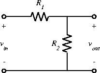 for which we have the familiar relation:
 or
or
 If
If  and
and  are fixed then the output voltage
is a constant fraction of the input,
i.e. we have a fixed attenuator.
If either or both of them vary, we have a variable attenuator
(e.g. a volume control).
If
are fixed then the output voltage
is a constant fraction of the input,
i.e. we have a fixed attenuator.
If either or both of them vary, we have a variable attenuator
(e.g. a volume control).
If  is constant and one or both of
or
vary with time, then
is constant and one or both of
or
vary with time, then  will be a function of time,
following the change in R
.
If either or both of
and
vary with frequency
(i.e. they are impedances rather than
pure resistances)
then the attenuation
(or
transfer function)
will be a function of frequency,
i.e. we have a
filter.
Finally, if one or the other of
or
is
non-linear, then the input-output relation will reflect
that nonlinearity.
will be a function of time,
following the change in R
.
If either or both of
and
vary with frequency
(i.e. they are impedances rather than
pure resistances)
then the attenuation
(or
transfer function)
will be a function of frequency,
i.e. we have a
filter.
Finally, if one or the other of
or
is
non-linear, then the input-output relation will reflect
that nonlinearity.
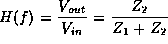
If we replace resistances
and
by impedances
 and
and  and use the phasor representation
(
and use the phasor representation
( and
and  ) for the input and output voltages,
then the voltage divider relation still holds.
We define the ratio of the output voltage phasor to the input
voltage phasor to be the
transfer function:
) for the input and output voltages,
then the voltage divider relation still holds.
We define the ratio of the output voltage phasor to the input
voltage phasor to be the
transfer function:
For example if we replace
with a capacitor, we get the following
circuit:
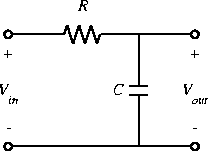 for which
Since H(f)
is close to one for small values of f
and goes to
zero for large f
(i.e. it passes low frequencies)
we call this circuit a
low pass filter.