ELEC 242 Lab
Experiment 4.3
Motor Amplifier
Equipment
- Standard Instrument Suite
- Standard Breadboard Set
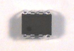
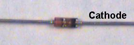
Components
The previous Experiment examined the inverting op-amp configurtion.
We'll now look at the voltage follower, an example of the
other major class of op-amp circuits: the non-inverting configurtion.
More significantly, we will boost the output drive capability with an
emitter follower buffer so that we can drive low resistance
loads, especially the DC motor, without distortion.
We will use this circuit in several subsequent labs, so devote some
care to building it. In particular, make it reasonably compact
and place it on the breadboard where it won't interfere with
building other circuits.
Here is a suggested layout for the final version of the circuit
(click for a larger view):
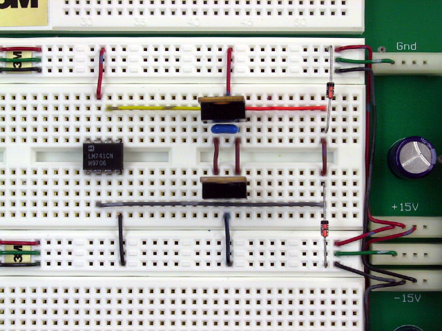 However you decide to lay out your circuit, use short wires.
Your circuit should be 2 dimensional, not 3 dimensional.
However you decide to lay out your circuit, use short wires.
Your circuit should be 2 dimensional, not 3 dimensional.
Part 1: Voltage Follower
| |
|

|
Step 1: |
|
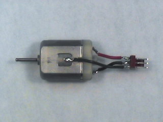
With the Ohms function of the DMM, measure the
armature resistance  of the motor.
Because of the commutator, this will vary with the shaft angle,
so rotate the shaft and take the average of several consistent
readings.
of the motor.
Because of the commutator, this will vary with the shaft angle,
so rotate the shaft and take the average of several consistent
readings.
|
Remark: |
|
To simplify testing
we will use a resistor as the load for our sequence of circuits
until the final step.
Last week we courted disaster (and burnt fingers)
by exceeding the power ratings of our transistor and load
resistor.
This week we will be a little more careful,
both by using components with higher ratings,
and by calculating levels to be sure that we
stay within them.
All the resistors in our parts kit are 1/4 W, but we
can make a load with higher power rating by connecting several of these
in series or parallel.
|
Step 2: |
|
Make a 50 ohm "power resistor" by connecting
the 5 10 ohm resistors in your kit in series.
Connect one end of this composite resistor to ground.
|
Question 2: |
|
Show that this composite resistor will dissipate
1.25 W without exeeding the power rating of any of the
individual resistances.
|
Step 3: |
|
Set the function generator to produce a 100 Hz,
1 V p-p
triangle wave.
|
Step 4: |
|
Connect the function generator output to the load resistor.
This should have the same effect as in Experiment 3.3,
i.e. the function generator output voltage should be reduced
by half due to the loading.
|
Step 5: |
|
Wire the following circuit
|
![\includegraphics[scale=0.650000]{ckt5.1.ps}](img217.png)
| |
|
|
Step 6: |
|
Connect  to the function generator output and
  to the load resistor.
|
Step 7: |
|
Observe
with the scope.
It should have an amplitude of 1 V p-p, i.e. there
should be no attenuation due to loading.
|
Step 8: |
|
Increase
until
begins to clip.
Note the value of
at which clipping occurs.
|
Step 9: |
|
Remove the load resistor and continue to increase
.
Does any clipping occur at the maximum output available
from the function generator?
|
Remark: |
|
From the spec sheet,  of the op-amp (open-loop) is about
75
of the op-amp (open-loop) is about
75 .
Yet we can drive a 50
load with no significant change
in amplitude.
In addition to reducing gain, negative feedback also reduces
output resistance.
So our inverting amplifier circuit, with feedback, has a very low
output resistance,
as long as everyting is linear.
What's happening when trying to drive a low load resistance to
large output amplitudes is that something nonlinear is happening:
current limiting.
The op-amp contains circuitry to prevent itself from being destroyed
by trying to deliver too much power.
When the output current reaches a limiting value (the
short-circuit current)
the op-amp stops increasing the output voltage.
This causes distortion of the output waveform,
but keeps you from having to replace the op-amp.
.
Yet we can drive a 50
load with no significant change
in amplitude.
In addition to reducing gain, negative feedback also reduces
output resistance.
So our inverting amplifier circuit, with feedback, has a very low
output resistance,
as long as everyting is linear.
What's happening when trying to drive a low load resistance to
large output amplitudes is that something nonlinear is happening:
current limiting.
The op-amp contains circuitry to prevent itself from being destroyed
by trying to deliver too much power.
When the output current reaches a limiting value (the
short-circuit current)
the op-amp stops increasing the output voltage.
This causes distortion of the output waveform,
but keeps you from having to replace the op-amp.
|
Question 3: |
|
Based on your measurements of the clipping level with a
50
load, what is the short-circuit current limit
of your op-amp?
How does this compare with the value in the spec sheet?
|
Part 2: Voltage Follower with Emitter Follower Output
Unfortunately, the
current the op amp is capable of delivering
is far too low to drive our motor with the
torque we will require from it.
We can fix this problem by using an emitter follower as a current
amplifier to increase the amount of current we can deliver to
a load.
Since
we're going to be delivering a lot of
power to the motor, and since our motor amplifier is not 100%
efficient, it's going to be dissipating a lot of power.
To keep from burning it (or our fingers) up, or
melting
the breadboard, we're going to have to get rid of the resulting
heat more efficiently.
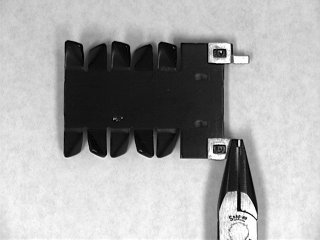
The way we will get this increased
heat dissipation
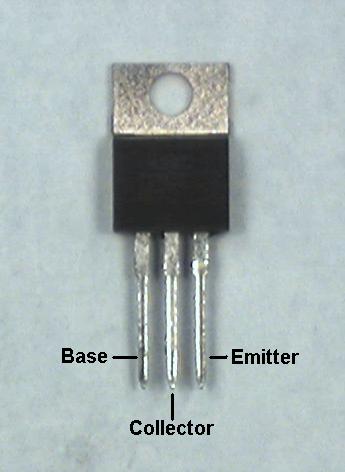
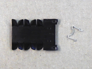
is by adding
heat sinks
to the transistors.
These are simply pieces of metal (aluminum) having high
thermal conductivity and large surface area which carry the
heat to a greater volume of ambient air than the small area of
the transistor case can.
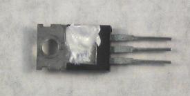
We will also use
heat sink compound
to improve the heat transfer from the transistor to the heat sink.
![\includegraphics[scale=0.650000]{ckt5.3.ps}](img219.png)
| |
|
|
Step 9: |
|
Set the function generator output to 3 V p-p.
Connect the function generator input to
and the load
resistor to
.
|
Step 10: |
|
Sketch the output waveform,
.
|
Step 11: |
|
Increase the function generator
AMPLITUDE
control to its maximum value.
Is there any clipping?
|
Part 3: Dead Zone Reduction
| |
|
|
Step 1: |
|
Move the feedback from around the op-amp to around the combination
of the op-amp and the emitter follower buffer.
Also add the
capacitor as shown. This is
another bit of magic, this time to try to
control oscillations.
|
![\includegraphics[scale=0.650000]{ckt5.5.ps}](img220.png)
| |
|
|
Step 2: |
|
Connect
to the function generator
and
to the load resistor, as in the previous part.
|
Step 3: |
|
With
a 3 V p-p triangle wave, sketch
.
|
Step 4: |
|
Increase the function generator
AMPLITUDE
control to its maximum value.
Is there any observable distortion in
?
|
Part 4: Driving the Motor
Now for the moment of truth:
Can we use this circuit to drive the motor and achieve an improvement
in performance?
| |
|
|
Step 1: |
|
Disconnect the 50 ohm load resistor.
|
Step 2: |
|
Wire the tip of J1-6 (pin 8 on the interface board socket strip)
to
. Wire the ring (pin 9) to ground.
|
Step 3: |
|
Set the function generator to produce a 10 Hz sine wave.
|
Step 4: |
|
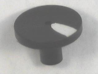
Press the strobe test disk onto the shaft of the motor.
|
Step 5: |
|
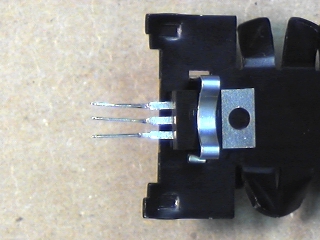
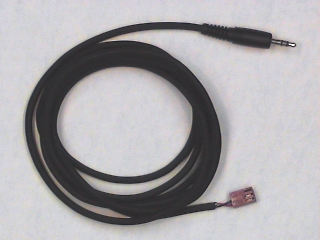
Plug a phone plug patch cord into J1-6 of the interface board.
Plug the motor into the 3-pin connector on the other end.
Be sure that the red wire on the motor lines up with the white
mark on the cable connector.
|
Step 6: |
|
Turn on the power and adjust the function generator
AMPLITUDE
control until the oscillation of the test disk is about 180 degrees.
|
Step 7: |
|
Disconnect the ungrounded side of the motor from
and connect
it directly to
(i.e. the function generator output).
What is the approximate angle of oscillation?
|
Step 8: |
|
Connect the
oscilloscope to the function generator and motor so that you
can measure the voltage across the motor.
|
Step 9: |
|
Set the function generator to produce a full scale 4 Hz square
wave.
Sketch the waveform of the voltage that actually appears across the
motor.
|
Step 10: |
|
Without changing the function generator settings,
reconnect the motor to
.
Sketch the waveform that now appears across the motor.
|
Step 11: |
|
Don't disassemble this circuit, as we will use it in subsequent Labs.
|
![\includegraphics[scale=1.000000]{scanl8b.ps}](img218.png)