The figure below is a schematic of the position control system.
As a simplification we have omitted the gearbox and absorbed its
effect into the values of ![]() and
and ![]() .
We have also absorbed the reflected moment of intrtia of the gears
and motor armature into
.
We have also absorbed the reflected moment of intrtia of the gears
and motor armature into ![]() .
.
![\includegraphics[scale=1.000000]{scan8.1.ps}](img241.png)
This translates into the following block diagram
![\includegraphics[scale=0.500000]{ckt8.7.ps}](img242.png)
 .
Integrating the angular velocity
.
Integrating the angular velocity ![\includegraphics[scale=0.650000]{ckt8.6.ps}](img243.png)
Previously we have used another motor as a tachogenerator to
measure speed.
We will be using a type of variable resistor known as a
potentiometer
to measure the angle of the gearbox output.
A
potentiometer
(or
pot
for short)
is a fixed value resistor with a third, movable contact
or
slider
which may be positioned anywhere along the
resistive element.
If we represent the position of the slider by
![]() , where
, where ![]() varies between 0 (fully counterclockwise)
and 1 (fully clockwise), then the resistance between the lower
end of the resistor and the slider will be
varies between 0 (fully counterclockwise)
and 1 (fully clockwise), then the resistance between the lower
end of the resistor and the slider will be ![]() and between
the slider and the upper end will be
and between
the slider and the upper end will be ![]() ,
where
,
where ![]() is the total resistance of the potentiometer.
is the total resistance of the potentiometer.
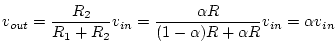
If we connect the two fixed contacts to a voltage source and measure the output between the movable contact and one fixed contact, we get a variable voltage divider:
![\includegraphics[scale=0.650000]{pot1.ps}](img244.png)
Then the output is
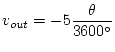
The potentiometer we are using is a
10-turn
pot, which means that ten turns
(![]() )
of the shaft are required to go from
)
of the shaft are required to go from
![]() to
to ![]() .
We will be using -5 V for
.
We will be using -5 V for ![]() , so
, so