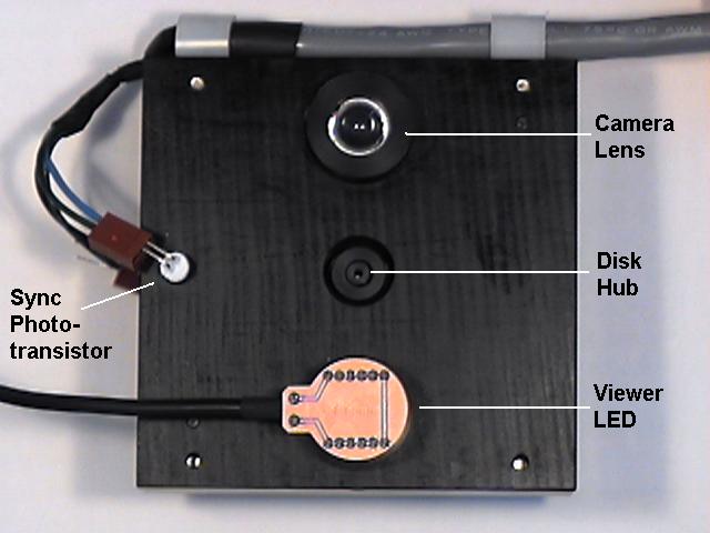
The camera is built around a large block of Delrin with the disk inside (shielded from ambient light) and all the various assemblies mounted to the outside. On the front are the camera lens and the viewer LED.
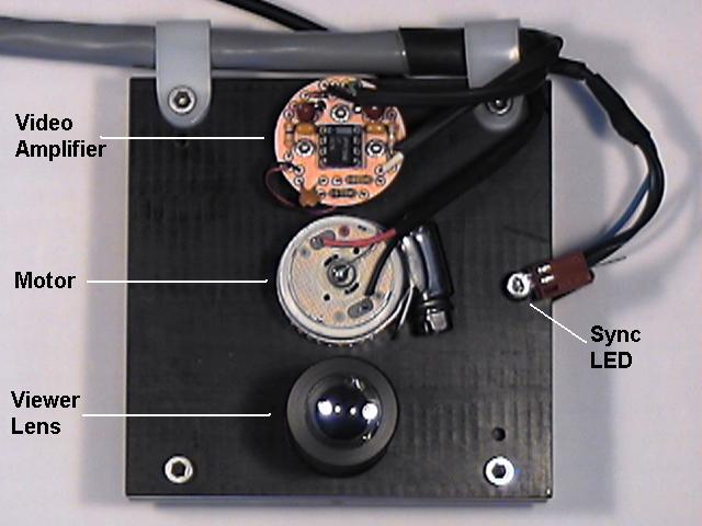
Here is a cross section of what's inside the camera:
![\includegraphics[scale=1.000000]{camera.ps}](img251.png)
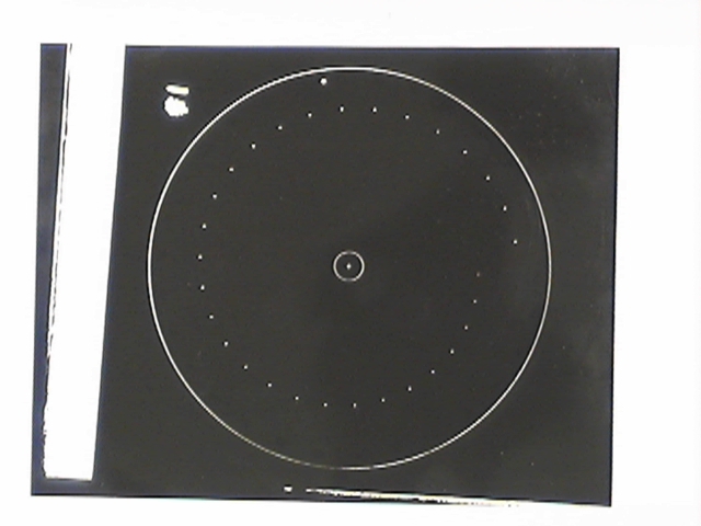
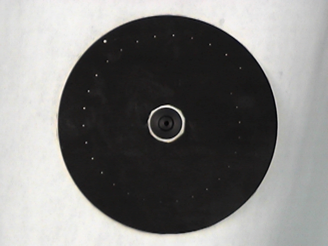
The disks are produced photographically from computer generated artwork. Here's the disk as it comes from the darkroom:
Because of the number of things on the camera that we need to connect to (the photodiode, the motor, the viewfinder LED, the synchronizer LED, and the synchronizer photodiode) we would run out of jacks if we tried to use phone plug cables to connect to the camera like we have for other external devices. Also, with so many different cables, all looking alike, it would be easy to plug one into the wrong jack, with possibly unpleasant results.
Fortunately, we have a connector with lots of pins that we aren't using: the sound card connector. So we will plug the camera (except for the photodiode output) into it, and reassign the pin numbers. Here are the new pin assignments:
| Pin | Signal | Conn | Function | Old Function |
| 14 | gnd | Ground | Ground | |
| 15 |
| J2-1 | video out | microphone |
| 16 | -15 V | J2-1 | -Vcc for opamp | speaker left |
| 17 | +15 V | J2-1 | +Vcc for opamp | speaker right |
| 18 | sound_lin_inl | J2-1 | sync LED anode | line in left |
| 19 | sound_lin_inr | J2-1 | sync phototransistor collector | line in right |
| 20 | sound_lin_outl | J2-1 | motor + | line out left |
| 21 | sound_lin_outr | J2-1 | motor - | line out right |
| 22 | gnd | Ground | Ground |