![\includegraphics[scale=0.650000]{motor1.ps}](img195.png)
An ideal DC motor looks like this schematically:
Some texts (including Cogdell) state these equations as
![]() and
and
![]() ,
to indicate the dependence
of the torque and back emf
on the strength of the magnetic flux (
,
to indicate the dependence
of the torque and back emf
on the strength of the magnetic flux (![]() ) in the motor.
In some types of DC motors
(so called
wound field
motors)
this flux may be changed by varying a second current,
called the
field current
(
) in the motor.
In some types of DC motors
(so called
wound field
motors)
this flux may be changed by varying a second current,
called the
field current
(![]() ).
In a permanent magnet motor,
).
In a permanent magnet motor, ![]() is fixed
by the strength of the permanent magnets,
so we will absorb the
is fixed
by the strength of the permanent magnets,
so we will absorb the ![]() into the constants
into the constants ![]() (and use lower case subscripts)
to simplify the equations.
(and use lower case subscripts)
to simplify the equations.
Just like a real battery departs from ideal because of its
internal resistance,
a real motor also contains a resistance,
called the
armature resistance
(![]() ) in series with an ideal motor.
This gives the following circuit:
) in series with an ideal motor.
This gives the following circuit:
![\includegraphics[scale=0.650000]{motor2.ps}](img196.png)
Now, although the armature current ![]() is still equal to the
current
is still equal to the
current ![]() flowing into the motor,
the voltage
flowing into the motor,
the voltage ![]() across the motor terminals is no longer equal to
the back emf
across the motor terminals is no longer equal to
the back emf ![]() .
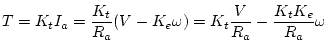
Instead we have, using KVL:
.
Instead we have, using KVL: ![]() .
Combining this with the coupling equations for the ideal motor,
we get:
.
Combining this with the coupling equations for the ideal motor,
we get:

If we apply a voltage source to a motor with no mechanical load
connected to it, then the torque produced by the current,
![]() ,
will act to accelerate the rotor of the motor.
However, as the velocity
,
will act to accelerate the rotor of the motor.
However, as the velocity ![]() increases,
it produces a back emf
increases,
it produces a back emf ![]() which opposes the applied voltage.
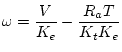
Thus, rather than continuing to accelerate indefinately, the
motor reaches an equilibrium
when
which opposes the applied voltage.
Thus, rather than continuing to accelerate indefinately, the
motor reaches an equilibrium
when
![]() where
where ![]() is called the
no load speed.
is called the
no load speed.
On the other hand, if we lock the rotor so that it can't turn
(i.e.
stall
the motor)
the current
![]() will continue to flow, producing
the
stall torque
will continue to flow, producing
the
stall torque
![]() .
Stated another way, if a load greater than
.
Stated another way, if a load greater than ![]() is required,
the motor will stop, or stall.
is required,
the motor will stop, or stall.
For values of load torque between zero and ![]() , we have
the relations
given above.
If we plot
, we have
the relations
given above.
If we plot ![]() vs.
vs. ![]() for a fixed voltage
for a fixed voltage ![]() ,
we get what is called a
constant voltage speed-torque curve.
If we change the voltage, the curve will move up or down,
giving a set of speed vs torque relations, one for each
voltage.
,
we get what is called a
constant voltage speed-torque curve.
If we change the voltage, the curve will move up or down,
giving a set of speed vs torque relations, one for each
voltage.
![\includegraphics[scale=0.650000]{speedtorque.ps}](img197.png)
In reality, the load torque is never zero. There will be some friction in the bearings, aerodynamic drag on the rotor, etc. Also, some types of motors have preferred orientations or detents where the magnets try to hold the rotor at a particular angle. This gives rise to a ripple torque which varies depending on the angle of the shaft. This will cause us some difficulty when we try to measure the torque characteristics of our motor, and can cause no end of grief when trying to use a motor with this characteristic in certain applications (fortunately not in ours).