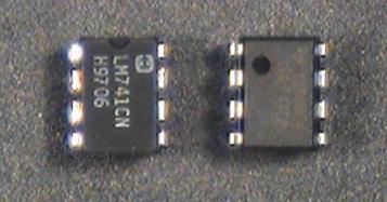
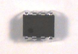
The 741 operational amplifier, or op-amp, comes in an 8-pin dual inline package (DIP) which looks like this
In order to function, the op-amp must be connected to an external
power supply.
Since we want to produce both positive and negative output
voltages, we need both positive and negative voltages
for the power supply.
These are labeled ![]() and
and ![]() on the diagram.
For a 741, the nominal values are
on the diagram.
For a 741, the nominal values are ![]() =15 V and
=15 V and
![]() =-15 V.
=-15 V.
To avoid clutter, we won't show the power supply terminals (pins 4 and 7) on any of the subsequent circuit diagrams. However, they must be connected or your amplifier will not operate.
Note that there is no ground terminal on the op-amp. The zero reference point is established by the external circuit and is not important to the op-amp itself.
|
| |||
Step 1: |
If you have not already done so, wire the bus strips on
your breadboard to provide positive power, negative power
and ground buses.
Whatever color scheme you have chosen for your wires, you
should use the green binding post for ground, the black for -15 V,
and the red for +15 V.
| ||
Step 2: |
Connect a 
These capacitors are the first of several bits of
"magic" we will employ to try to avoid amomolous behavior.
As we will see when we study control systems,
feedback also has a dark side.
In particular, feedback which becomes positive at some frequency
can cause instabilities.
Although we have not deliberately introduced any positive feedback,
feedback can occur where we don't intend it.
The purpose of these capacitors is to prevent it from occurring
via the power supply, which at high frequencies is not a very
ideal voltage source.
| ||
Step 3: |
Plug an op-amp into the breadboard so that it straddles the gap
between the top and bottom sections of the socket strip.
If you have wired the power buses as suggested above, Pin 1 should
be to the left.
| ||
Step 4: |
Connect Pin 4 (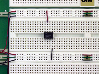
| ||
Step 5: |
Set the
METER SELECTOR
on the power supply to
+20V.
With the power supply disconnected from the breadboard,
turn on the supply and adjust the left-hand voltage control
until the meter reads 15 volts.
| ||
Step 6: |
Turn off the supply and connect the supply to the breadboard with banana plug patch cables. Connect the 0 to -20V terminal (black) to the black binding post on your breadboard, the 0 to +20V terminal (red) to the red breadboard binding post, and the COMMON terminal (light blue) to the green breadboard binding post. Note that none of the power supply output terminals are connected to ground. If we want the power supply zero volt reference connected to ground, we must make the connection ourselves. |
| |||
Step 1: |
With the power turned off,
wire the following circuit.
This will compare the function generator output with an adjustable
threshold proficed by the 0-6V supply.
| ||
Step 2: |
Set the function generator to produce a 4 V p-p,
100 Hz triangle wave.
| ||
Step 3: |
Pull out the
DC OFFSET
control and adjust it so that the waveform has an average value
of 2.5 V (i.e. the negative peaks have a value of +0.5 V).
| ||
Step 4: |
Connect the function generator output to | ||
Step 5: |
Turn on the power supply and set the
0-6V
output to zero.
| ||
Step 6: |
Slowly increase the
0-6V
control until | ||
Step 7: |
Increase | ||
Step 8: |
Set | ||
Question 1: |
Explain the waveforms observed in this Part.
Develop an expression for the
duty cycle
(the percentage of the time that the waveform is in the "high"
state)
as a function of |