In
Part 4 of Experiment 1.1
we found that the resistance of the light bulb
filament increased with increasing temperature.
Materials
(such as metals)
which exhibit this behavior are sead to
have a
positive temperature coefficient.
Materials
(such as semiconductors)
whose resistance decreases with temperature
have a
negative temperature coefficient
(NTC).
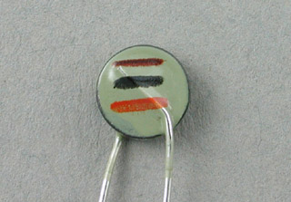
The thermistor is a piece of NTC material whose resistance
is described by the equation
 ,
where
,
where  is the resistance at the measured temperature
  and
and  is the resistance at the reference temperature
  .
Note that the temperatures must be absolute temperatures (in K).
.
Note that the temperatures must be absolute temperatures (in K).
| |
|

|
Step 1: |
|
In this experiment
we will need to make resistance measurements in
situations where using the DMM probes
or banana plug patch cords will not be satisfactory.
Fortunately, there is very convenient way to do this.
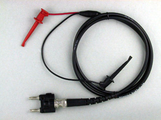
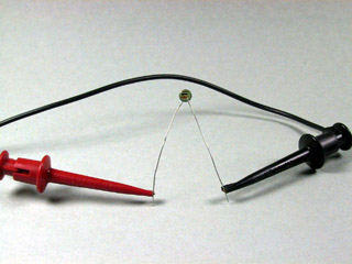
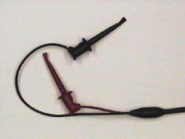
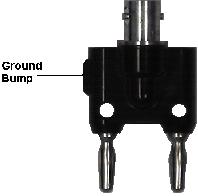
Get a
BNC clip lead cable
from the equipment room and attach it to the
BNC-banana adapter
from your tool kit, thereby creating a
banana plug clip lead cable.
 Plug the banana plug end of this assembly into the
V
and
COM
terminals of your DMM
and set the selector switch to Ω.
Plug the banana plug end of this assembly into the
V
and
COM
terminals of your DMM
and set the selector switch to Ω.
|
Step 2: |
|
Connect the clip leads to the terminals of the thermistor.
|
Step 3: |
|
Wait until the resistance reading on the DMM has stabilized,
and record the value.
This represents the ambient room temperature.
|
Step 4: |
|
Devise a means of placing the thermistor in intimate contact
with your body (or your lab partner's body).
When the resistance reading has stabilized, record the value.
|
Question 5: |
|
Based on the nominal values for resistance and B value,
what are the ambient temperature
and your (or your lab partner's) body temperature?
|
| |
|
|
Step 1: |
|
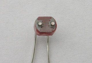
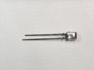
Remove the CdS photocell from the clip leads
and replace it with the photodiode.
|
Step 2: |
|
Set the DMM selector to DC Volts.
|
Step 3: |
|
Observe the changes in voltage produced by the photodiode
as the amount of light reaching it is changed.
Record the voltages for the same conditions you did
for the CdS photocell in Part 2.
|
Step 4: |
|
Examination of the data sheet for the photodiode
shows that it is the
current
rather than the
voltage
which is proportional to the incident illumination.
Set the DMM to DC Current and connect the
clip leads to the
COM
and
300 mA
terminals.
(Since the spacing between these two terminals is
not the same as the spacing between the plugs on
the banana plug adapter, you will have to insert
one plug into one of the terminals and use a
banana plug patch cord to connect the other.)
|
Step 5: |
|
Observe the changes in the current produced by the photodiode
as the amount of light reaching it is changed.
Record the current values for the same conditions you did
previously
in Part 2
and Step 3.
|
Question 7: |
|
Based on the nominal characteristics of the photodiode,
what is the ambient illumination level in the lab?
What is the illumination level at a distance of one foot from
the incandescant lamp?
How do these values compare with those measured with the CdS photocell?
|