|
| ||
Step 1: |
Set up the function generator to produce a 1kHz sine wave
with a peak to peak (p-p) amplitude of 5 volts.
| |
Step 2: |
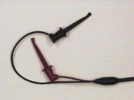
Using the
BNC clip leads,
connect the output of the function generator to the speaker.
What do you hear?
| |
Step 3: |
With the speaker still connected to the function generator, measure
the amplitude of the voltage across the speaker
(use a second BNC clip lead).
Is it the same as in Step 1?
| |
Step 4: |
Using the controls on the function generator,
vary the amplitude, frequency, and waveshape
(i.e. sine, triangle, or square)
of the signal.
How does the nature of the sound change as these
signal parameters change?
| |
Step 5: |
Disconnect the speaker. |
If we consider the following circuit:
![\includegraphics[scale=0.650000]{../241/fig4.ps}](img221.png)
|
| ||
Step 1: |
Using the BNC clip leads,
connect the speaker to
CH1
of the oscilloscope.
| |
Step 2: |
Set the
VOLTS/DIV
switch to
20 mV
and the
TIME/DIV
switch to
2 mSEC.
| |
Step 3: |
Speak into the loudspeaker and observe the waveform on the oscilloscope. If necessary, adjust the oscilloscope to produce a satisfactory trace. Note the amplitude of the signal. |
|
| |||
Step 1: |
Get a microphone from the equipment cart.
It has two connectors, one slightly smaller than the other.
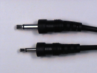
We want to use the scope to measure the microphone's output,
but attempting to connect the clip leads to the microphone
connector is an exercise in futility. So ...
| ||
Step 2: |
Use a BNC
patch cord to connect
CH1
of the scope to J1-1 of the
interface module.
| ||
Step 3: |
Plug the microphone into J1-4 of the
interface module.
Take a piece of wire about 4 cm long and strip
6 to 7 mm
of insulation from each end.
The end of the wire should look like this:
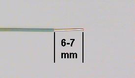
Connect the microphone to Channel 1 of the scope by plugging one end of the wire into pin 1 of the socket strip and the other end into pin 4. The grounds are connected automatically by the interface board. 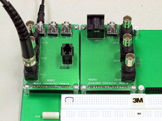
| ||
Step 4: |
Set the oscilloscope
V MODE
switch to
CH1,
the
CH 1 VOLTS/DIV
switch to
5 mV,
and the
TIME/DIV
switch to
1 mSEC.
Set the other controls as required.
| ||
Step 5: |
Speak, sing, or whistle into the microphone
and observe the signal on the scope.
If the amplitude is too small, you can use the
magnifier
to get a little more gain.
Pull out the
POSITION
knob
(the
VARIABLE
knob on the Leader)
to increase the gain
(thereby
decreasing
the Volts/Div)
by a factor of 5
(10 on the Leader).
| ||
Diversion: |
The triggering controls
(Auto/Norm, Level, Slope, and Coupling (and Holdoff on the Leader))
determine the relationship between the origin of the display
(t=0) and features of the waveform.
In
AUTO
mode, the beam sweeps continuously, whether a signal is present
or not
and attempts to synchronize
automatically
when a signal is applied.
This usually works well for simple signals, such as those produced
by the function generator, but often results in an unstable display
with more complex signals, such as speech signals.
For these signals,
NORMAL
mode is often more appropriate.
In normal mode
a sweep is started only when the signal being displayed
crosses a specified threshold.
The level of the threshold is controlled by the
LEVEL
knob, and the direction of crossing by the
SLOPE
control.
| ||
Step 6: |
Set the
AUTO/NORM
control to
NORM.
Speak into the microphone and adjust the
LEVEL
control to produce a stable display.
Experiment with the triggering controls and the
TIME/DIV
control to see what effects they have on the display.
| ||
Step 7: |
Measure
the amplitude of the signal.
(Remember to include the scale factor if you used the magnifier.)
| ||
Step 8: |
Produce a sustained vowel (a, e, i, o, u) sound.
Sketch one or two of the more interesting waveshapes.
| ||
Step 9: |
Continue producing a sustained vowel sound
(inhaling as necessary) and measure its
frequency (by measuring the period).
| ||
Step 10: |
(Optional)
If you are musically inclined,
sing (or whistle or hum) the note "A"
and measure its frequency.
(If you play an instrument and have it with you, use it to
produce your note.)
How does your measured frequency compare with the "official"
value for the frequency of A?
Which do you trust to be more accurate, your sense of pitch
or the oscilloscope?
| ||
Step 11: |
Whistle softly into the microphone.
(For this step, pitch is not important, so any note
will do.)
Observe the waveform on the oscilloscope.
Is it sinusoidal?
| ||
Question 3: |
Based on your measurements of the loudspeaker sensitivity and the output of the microphone, would it be possible to produce an audible sound in the loudspeaker by connecting it directly to the microphone? |