Step 1:
Step 2:
Last week we used the photodiode to measure the ambient illumination level and other apparantly DC values. In fact the light in the lab has a significant AC component whose frequency is faster than our eyes can perceive. By using the oscilloscope to observe the photodiode output signal, we can separate the AC and DC components of the light level.
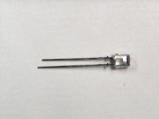
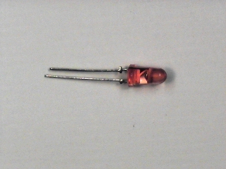
With certain materials, the process by which the photodiode converts photons to electrons can be run in reverse, converting electricity to light. The photodiode we are using is made of silicon, which is not one of those materials. However, in our parts kit are a number of diodes which are made out of such a material (e.g. gallium phosphide) which can convert electrons to photons. These diodes are called, somewhat unimaginatively, light emitting diodes or LEDs.
|
| ||
Step 1: |
Set the oscilloscope controls as follows:
V MODE
switch to
CH1,
CH1 VOLTS/DIV
switch to
.2 V,
CH1 AC-GND-DC
switch to
DC,
and the
TIME/DIV
switch to
2 mSEC.
(Use your own experience to select the remaining settings.)
| |
Step 2: |
Connect the short lead (cathode) of the
photodiode
to ground
and the long lead (anode) to
CH1
of the scope.
You can use the BNC clip leads for this, but a better way
(which leaves your hands free) is to plug it into the breadboard
and wire it to the socket strip on the
interface board.
(With the interface board connected as described above, pin 1
will be
CH1
and pin 14 will be ground.)
| |
Step 3: |
Use the
GND
position of the
CH1 AC-GND-DC
switch to establish the zero reference.
Return the switch to the
DC
position.
| |
Step 4: |
Note the voltage produced by the photodiode.
How does it change when you cover the photodiode with your hand.
| |
Step 5: |
Repeat the previous two steps using as a source
(a) the under-shelf florescent lamp and
(b) the incandescent lamp.
Sketch the shape of the AC component of the waveform
for each source.
What is its amplitude and frequency?
| |
Remark: |
The following procedure may make it easier to study the
AC component of the signal:
Set the
CH1 AC-GND-DC
switch to the
AC
position and the
VOLTS/DIV
switch to
5 mV.
Pull out the
CH1
magnifier.
Adjust the timebase to produce a stable trace.
| |
Question 4: |
Explain the waveforms you observed in the previous Step. |
Since the oscilloscope (and the Lab PC) can only display voltage, we need to convert the current produced by the photodiode (called photocurrent) to a voltage in order to make quantitative measurements. We will find more sophisticated ways of doing this in Labs 5 and 6, but for now the only technique we have is to send the current through a resistor and allow Ohm's law to give us a proportional voltage.
|
| ||
Step 1: |
Keeping the setup from the previous Part,
connect a 1~sp kΩ resistor
(brown-black-red) in parallel with the photodiode.
| |
Step 2: |
Adjusting the VOLTS/DIV switch as necessary, repeat the measurements of Part 1 using the same three light sources (overhead florescent lamps, under-shelf florescent lamp, incandescant lamp). |
|
| |||
Step 1: |
Set up the power supply: turn both voltage controls to zero
and set the meter selector to the 6V supply.
Don't connect the supply yet.
| ||
Step 2: |
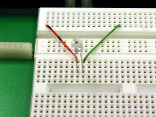
Using a 220 ohm (red-red-brown) resistor and your
red LED,
wire the following circuit.
![\includegraphics[scale=0.650000]{../241/ckt2.3.2.ps}](img222.png)
First wire the resistor and LED on the breadboard. 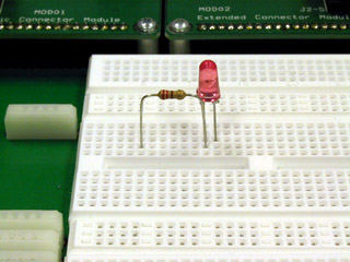
The first way: Plug your BNC-banana adapter into the 6V supply terminals. 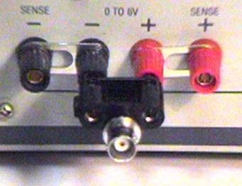
Then use the clip leads to connect to the LED and resistor. 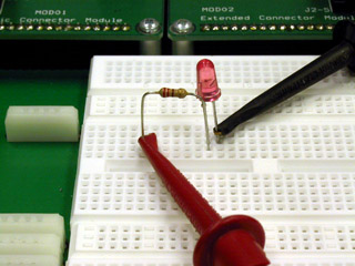
The other way: Use the BNC adapter as above, but use a BNC patch cord to connect the power supply to J1-3 on the interface board. Use two pieces of wire to connect ground (pin 14) to the LED and the J1-3 signal (pin 3) to the resistor. 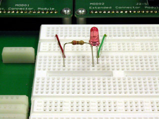
| ||
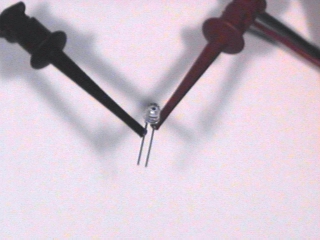
Step 3: |
Turn on the power supply.
Slowly increase the voltage until you see the LED just begin to glow.
Measure the voltage across the LED.
If the LED doesn't light by the time the meter on the power supply
reads 3 V, check your circuit to make sure the diode is wired
in the correct orientation.
Unlike a resistor or light bulb, the LED is
polarized.
The anode must be positive for it to glow.
Reverse the LED and verify that this is the case.
| ||
Step 4: |
Set the supply voltage
(as read by the front panel meter) to 3, 4, and 5 volts.
At each step note the brightness of the LED and the
voltage across it.
| ||
Step 5: |
Disconnect the BNC cable from the power supply and connect it to
the
Main Output
of the function generator.
Leave the other end connected to J1-3 of the Interface board.
| ||
Step 6: |
Set the function generator to product a 100 Hz
square wave.
Make sure the -20dB Attenuator is IN
and set the amplitude to minimum.
| ||
Step 7: |
Increase the function generator amplitude until the LED begins
to glow.
Is the glow steady?
| ||
Step 8: |
Slowly reduce the frequency of the function generator.
At what frequency does the appearance of steady glow stop
and noticeable flicker begin?
| ||
Question 5: |
How does the number you measured in the previous step relate to the frame rate of television and motion pictures? |
|
| ||
Step 1: |
Disconnect the BNC patch cord from
CH1
of the scope and connect the BNC clip leads.
Connect the photodiode to the clip leads.
| |
Step 2: |
With the LED still connected to the function generator
as in the previous part, set the frequency to 100 Hz.
| |
Step 3: |
Hold the photodiode (pointing down) above the LED
(pointing up).
Adjust their relative positions to maximize the signal
displayed on the scope.
(It may help to shield the components from ambient light with
your hand.)
Describe the waveform.
Is it what you would expect?
| |
Step 4: |
Set the function generator to produce a triangle wave.
Sketch the waveform you see on the scope.
Is it what you expected?
Can you explain it?
| |
Step 5: |
Reset the function generator to produce a square wave. Slowly separate the photodiode from the LED, adjusting the alignment to maintain the best signal. What is the maximum distance over which you can transmit a recognizable signal. Hint: switch the scope to the AC position and increase the gain. |