ELEC 243 Lab
Prelude
Measuring the Transfer Function
Computing and plotting the expected transfer function of
an RC circuit is easy: just use Matlab.
When it comes time to measure the actual transfer
function in the lab, things are a bit harder.
One obvious difficulty is that instead of simply making the
measurement at a single frequency (e.g. zero),
we have to make it at
all
frequencies,
a rather daunting task.
Fortunately, the function we expect to get is well behaved,
so a few judiciously chosen frequencies should suffice.
The other problem is that we have to measure both the
magnitude and the phase of the input and output signals.
We already know how to measure magnitude.
Let's see if we can figure out how to measure phase.
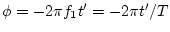
We will use the following technique:
-
Connect the function generator to the input of the system
being measured:
![\includegraphics[scale=0.650000]{freq_resp.ps}](img260.png)
-
Connect
CH1
of the scope to
 and
CH2
to
and
CH2
to  .
.
-
Set the
V MODE
switch to
DUAL (CHOP).
-
Set both
AC-GND-DC
switches to
DC.
In a case where there is a DC offset on either the input or the output,
you will have to set the corresponding switch to
AC.
If you do so, be aware that this will influence the
low frequency portion of the measurement
(below about 20 Hz).
-
Set the function generator
AMPLITUDE
control to zero.
Use the
POSITION
controls to align both traces with the X-axis.
-
Set the function generator frequency to the
first frequency to be measured, say
 .
Set the function generator
AMPLITUDE
control
to give a convenient number
(e.g. 1 or 2 volts) for the amplitude of
.
.
Set the function generator
AMPLITUDE
control
to give a convenient number
(e.g. 1 or 2 volts) for the amplitude of
.
-
Adjust the
VOLTS/DIV,
TIME/DIV,
horizontal
POSITION,
and trigger
LEVEL
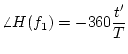
controls until the display looks similar to this:
![\includegraphics[scale=0.650000]{phase.ps}](img261.png) In particular, you should have just over one cycle of the
input waveform displayed, and it should cross the X-axis
at the leftmost vertical division.
In particular, you should have just over one cycle of the
input waveform displayed, and it should cross the X-axis
at the leftmost vertical division.
Let's see what we've got:
-
By measuring the height of the peaks of
CH1
we get
 .
.
-
Similarly, the peaks of
CH2
give
 .
.
-
Calculate
 .
.
-
Measure
 , the distance between successive zero crossings of the
same slope.
This zero crossing corresponds to
, the distance between successive zero crossings of the
same slope.
This zero crossing corresponds to
 for
and
for
and
 for
, where
for
, where
 .
So we have
.
So we have
 or
or
 ,
where
,
where  is the period of the waveform.
This gives the phase in radians. To the the phase in degrees, we
would use:
is the period of the waveform.
This gives the phase in radians. To the the phase in degrees, we
would use:
This gives us the magnitude and angle of the transfer
at a single frequency,
.
To get the complete transfer function, we repeat the procedure at
our "judiciously chosen" frequencies.