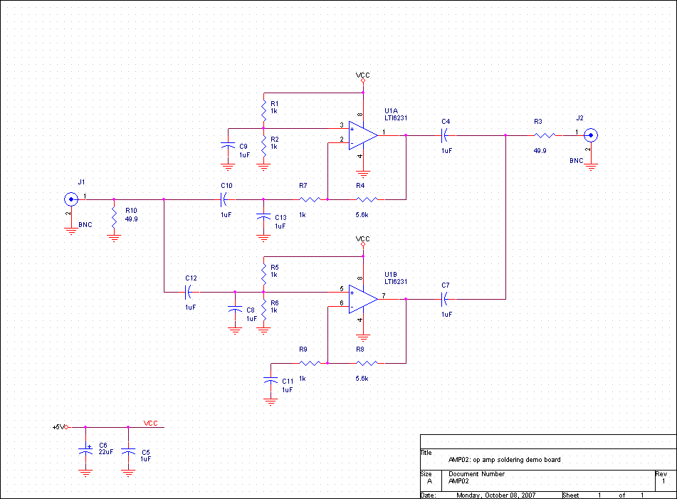
Actually, as you can see there are two amplifier circuits on the board, one inverting and one non-inverting. However, since there is only one pair of BNC connectors, we can only use one of them at a time. By installing and removing various capacitors we can select which amplifier is connected and which is disabled. (To enable the non-inverting amplifier, omit C4, C8, and C10. To enable the inverting amplifier, omit C7, C12, and C13.)
The components on the front of the board are labeled, but because of the ground plane, those on the back aren't. Here are the component locations for the back side of the board:
