ELEC 332
In the Lab I: Assembly
Part 1: The Components
Here's a picture of the various surface mount components we
will use for our amplifier circuit.
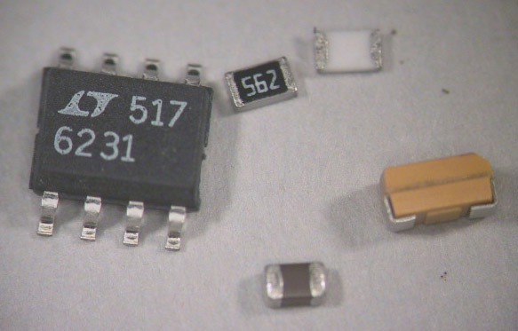 The big dark gray package with eight legs is the op-amp
(the part number (6231) stenciled on top is a big clue).
If you look closely, you can see that the edge toward the
bottom of the picture is beveled. The leftmost pin on this edge
(the pin nearest the "6" in the part number) is pin 1.
The black package with white lettering is a resistor.
The plain white package is the underside of a resistor.
The brown package is a capacitor (it looks the same on all sides).
SMD resistor and capacitor packages are described by their size.
These are 0805 packages which are .08 inches long and .05 inches wide.
The orange package is an electrolytic capacitor.
Again, close examination reveals a beveled edge, in this case
marking the positive terminal.
The big dark gray package with eight legs is the op-amp
(the part number (6231) stenciled on top is a big clue).
If you look closely, you can see that the edge toward the
bottom of the picture is beveled. The leftmost pin on this edge
(the pin nearest the "6" in the part number) is pin 1.
The black package with white lettering is a resistor.
The plain white package is the underside of a resistor.
The brown package is a capacitor (it looks the same on all sides).
SMD resistor and capacitor packages are described by their size.
These are 0805 packages which are .08 inches long and .05 inches wide.
The orange package is an electrolytic capacitor.
Again, close examination reveals a beveled edge, in this case
marking the positive terminal.
It is possible, and often necessary, to mix thru-hole and surface mount
components on the same board. Our final components, the BNC jacks,
are thru-hole components.
Part 2: The Finished Product
When it's all finished, your board should look like this (from the top):
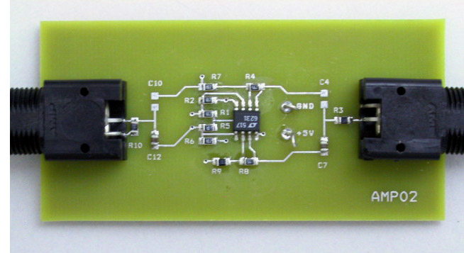
Another advantage of surface mount technology is that you can
use both sides of the board.
Most of the capacitors are on the bottom of the board,
which looks like this when finished:
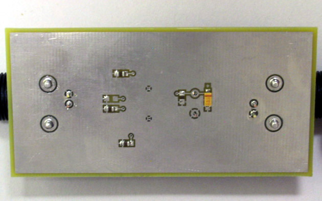
Note that both of these photographs are of a board configured to
use the non-inverting amplifier.
Part 3: Tools and Materials
- Magnifying Devices
-
The components on our board are among the largest surface mount components
available, i.e. they aren't really all that small.
If you have reasonably good eyesight, you can probably assemble this circuit
without any optical aids.
If you need a
modest amount of visual assistance, you can use one of the
Optivisors which provide 2.5x stereoscopic magnification.
If you
really
want to be able to see what you're doing then use the
stereo microscope.
It provides
7-30x variable magnification
along with bright, even illumination.
- The Vise
-
The most convenient tool for holding small circuit boards like this
one is the Palmgren vise. It provides enough mass to hold the board
stable, but the smooth, flat bottom allows for easy repositioning
and reorientation.
- Tweezers
-
Next we need something to hold the components.
Fingers are less than ideal because
(a) they're too big, and
(b) we need to be holding the component while it's being
soldered (i.e. getting very hot).
There are a number of possiblities, including
glue, vacuum pickups,
and tweezers.
We have several styles of tweezers, including broad tipped,
straight fine point, and curved fine point.
Choose whichever suits the particular situation
(or your style) best.
- Soldering Irons
-
For surface mount soldering, it's important to have a heat source
(soldering iron)
with an appropriately shaped and sized tip,
accurately controlled temperature,
and the ability to deliver an adequate amount of heat
without significant drop or rise in tip temperature.
- Xytronic 137ESD
-
The Xytronic iron is good for general purpose
soldering, but most of the tips are too large for
surface mount work,
and the handle-to-tip distance is too long for precise control.
For more information, see the
137ESD User Manual.
- OK PS-800
-
The PS-800 is the easiest iron to use and has the greatest
variety of available tips.
There's only one control: ON/OFF.
The operating temperature is set by the tip itself and
requires no adjustment.
The tips are very easy to change:
First turn off the power (changing the tips with the power on can
damage the heating system).
Grasp the tip with the black silicone pad (tethered to the iron's cord)
and pull gently.
Place the hot tip in one of the grooves on the side of the stand to cool,
select a new tip, and press it firmly in place.
DON'T
use pliers to change the tips.
For more information, see the
PS-800 User Manual.
- Weller WD2M System
-
This system includes the WD2M control unit,
WMP soldering iron, and WMRT thermal tweezers.
The WMP iron
is about the same size and shape
as the PS-800 iron, but that's where the simularity ends.
It is significantly more complicated than the OK system
and
has tips which, although fairly easy to change,
are also fairly easy to burn yourself with while changing.
It does have at least two things going for it:
It will turn itself off if left unused for
a certain amount of time,
and it supports a very nice pair of thermal tweezers (WMRT).
Like the Xytronic, and unlike the OK, it provides continuously
adjustable tip temperature.
However, since the WD2M is a two-channel unit,
but only has a single display, some deft finger
work is necessary to utilize this feature.
To select the channel to be displayed, press either
the button labeled "1" (for the soldering iron)
or "2" (for the thermal tweezers).
Immediately
after a button is depressed, the display
shows the "set" temperature.
After a few seconds, the display changes to show
the actual current temperature.
To change the set temperature, use the up and down
arrow buttons.
Use of either of these buttons also changes
the display to the set temperature for a few seconds.
The tips on the WMP iron are threaded, rather than press fit.
To change tips, turn off the iron, grip the tip either using the
black silicone pad from the PS-800 or the rubber handled socket wrench
(normally stored in the back of the WMP stand),
unscrew it, and place it in the rack.
Select the new tip, slide it on, and screw it in firmly, but
not too tightly.
If you use the
socket wrench, remember that by the time you have removed the old tip
and placed it in the rack, the metal portion of the wrench will be
almost as hot as the tip you removed.
For detailed instructions, see the
WD2M User Manual.
-
-
A few general rules:
The optimum tip temperature for the kind of work we will be doing
is about 650°F.
Never set the tip temperature above 750°F.
High temperatures greatly reduce the life of the tip
and increase the risk of damage to your circuit board or components.
Always turn the iron off when not in use.
Leaving it on overnight (or worse, over the weekend) may
cause the tip to become oxidized beyond recovery.
- Tips
-
All of our soldering irons have interchangeable tips.
A few (like the mini-hoof tip) are for special purposes,
but most are simply different sizes and shapes of general
purpose tips.
The temptation when soldering small stuff is to use the finest
tip available.
In fact you should use the largest
tip which will fit the joint.
The idea is to get the necesssary
amount of
heat into the joint as quickly as possible,
melt and flow the solder,
and get out before other parts
of the board or chip have a chance to heat up.
The best tip to use will have a broad, flat surface to
provide maximum contact area between the tip and the joint.
Tips of this type include chisel shaped tips, with two flat faces,
and beveled tips with just one.
Unfortunately, it is not possible to make chisel tips smaller than
about 1 mm.
Where a finer tip is required, conical tips are available with points
as small as 0.25 mm.
- Solder
-
Solder is an alloy containing 63% tin and 37% lead.
This is a
eutectic
mixture, which has the lowest melting point of any
mixture of these two elements (361°F or 183°C).
Because solder contains lead, you should wash your
hands thoroughly after each soldering session.
We have spools of wire solder in two sizes: small (0.015 in. dia.)
and medium (0.030 in. dia.).
- Flux
-
Flux is necessary to
remove the film of oxide on the surfaces of the materials to be joined
and to protect them from additional oxidation during the soldering
operation.
The solder "wire" is actually a solder tube.
It has a hollow core which is filled with flux.
The amount of flux provided by the solder is
usually sufficient to form a satisfactory joint.
However, in some circumstances
(e.g. soldering bare copper, unusually dirty joints, or when
using the mini-hoof tip) it is necessary to add additional flux.
This is available in liquid form in a
flux pen
(for large areas)
or in gel form in a fine-tipped syringe
where a small, controlled amount is required.
All of the fluxes we have are of the
no-clean
variety,
which means that the flux
residue can be left on the board without
undesirable effects.
If you find the flux residue esthetically offensive,
it can be removed,
using either isopropyl alchohol or the can of
aerosol flux remover.
If you do decide to remove the flux, be prepared to
do a very thorough job.
Simply spraying some flux remover on the board and
scrubbing it around with the brush will leave big streaks
of flux all over the board, rather than small spots of
flux on the joints.
- Stands and Sponges
-
Each iron has its own custom stand to hold it when not in use.
In the base of each stand is a sponge which is used to clean the tip.
This sponge should be
kept moistened (but not too wet) with water.
Each time you pick up the iron from the stand, wipe the tip twice
(once on each side) against the sponge. The thermal shock loosens
the oxide and the cushion of steam prevents the tip from burning the
sponge.
- Thermal Tweezers
-
The final two items on our list are used primarily for
unsoldering.
The thermal tweezers is simply a pair of small soldering irons
attached together like the two halves of a pair of tweezers.
If you grasp a surface mount resistor or capacitor between the tips,
the solder on each end will be melted and the component can be
lifted off of the board.
- Hot Air System
-
The
Xytronic 850D hot air tool produces a stream of
very
hot air (the same temperature as the tip of a soldering iron).
By directing this air flow
onto the pins of a multi-lead package
it's possible to melt the solder on all of the pins simultaneously,
thereby releasing the component.
It's important not to set the flow rate too high.
On a crowded board it's possible to literally blow away
a swath of components which you had not intended to remove.
For the small, angled tip, the minimum rate (1) is about right.
For the large round tip, try a setting of 3 to 3.5.
The temperature should be set to about 340°C.
For more information, see the
850D Instruction Manual.
Part 4: Soldering
Now that we've been introduced to the cast, it's time for the
show to begin.
The plot is very simple: take all of the components out of the bag
and solder them onto their proper places on the board.
Unlike thru-hole components which stay put while you're soldering them,
surface mount components will slide around until at least one of their
leads is soldered to hold it in place.
To avoid the need for three hands
(one to hold the component (with tweezers), one to hold the iron, and one to
hold the solder), we use a three step procedure.
First we apply the necessary amount of solder to one of the pads
(solder in one hand, iron in the other).
Next we remelt the solder and hold the component in place till the solder
resolidifies (tweezers in one hand, iron in the other).
Finally, with the component firmly held in place by this first pin, we solder
the remaining pin(s) in the conventional manner (solder in one hand,
iron in the other).
While this is simple enough in theory, in practice there are some
subtleties involved which are probably best seen rather than read about.
To see this process in action, you can watch the
SMD Soldering Video.
Part 5: Unsoldering
Ideally, once you've soldered all of the components onto your
circuit board, it will work correctly the first time and will
continue to work for years to come (or at least until the end
of the semester).
In reality, mistakes will be made, components will be defective
or will fail,
and it will be necessary to remove components from the
board and replace them with new ones.
This will require us to undo the previous soldering, or
unsolder
the wayward components.
Although we have to solder the components to the board one pin at a time,
we need to remove them by unsoldering all the pins simultaneously.
Most techniques for removing SMDs one pin at a time run the risk of lifting
a pad.
To see examples of these unsoldering techniques,
watch the
SMD Unsoldering Video.