ELEC 332
Background
Introduction
Many of the chips we will be using in subsequent
weeks are programmable.
This provides substantial flexibility and control
but means that
we can't use them until we
have something to program them with.
The simplest way
(and the one we'll use)
is to use a microcontroller,
but other possibilities include DSPs, FPGAs, or more
powerful microprocessors.
Since a typical microcontroller is generously endowed
with assorted inputs and outputs, including analog,
it can perform a number of useful functions on its own,
perhaps with the help of a few discrete components.
MSP430
The microcontroller we will be using during the next few weeks
is the Texas Instruments MSP430F2012, the same chip that was used
in ELEC 220.
The 2012 is near the bottom of the MSP430 lineup in terms
of available resources (e.g. memory, special functions, I/O ports).
In particular, it has only 14 pins.
By the time we've taken care of essentials like power and debug interface,
there are very few left to connect to the things we want to control.
However, it's inexpensive and familiar, so we will use it
until it runs out of steam, then move up to a more powerful
member of the family.
Although most microcontrollers
(including the MSP430)
have lots of analog inputs, many
(including most of the MSP430 family)
have no conventional D/A outputs.
Fortunately there are a number of ways around this shortcoming,
including external D/A chips and the use of digital outputs to
produce analog signals using a technique called
pulse width modulation
or PWM.
ELEC 332 Breadboard
In designing a system
there is a tradeoff between placing everything
on a single circuit board,
thereby reducing size and cost,
or dividing the system into a number of interconnected
modules,
which increases size and cost, but makes development and
maintenance easier.
Since we will be building a number of different systems this semester,
ease of development and reusability of work are more important than
size and cost.
The breadboard we used in 241 and 242
provided these features to some extent,
but is unable to support the level of performance we require
for this course.
To get this performance we will have to construct our circuits
on printed circuit boards,
such as the one we built last week.
That circuit
was a nice, self-contained module.
All we needed to do was to connect to the inputs and outputs with
BNC cables and to the power supply with clip leads and we were
ready to go.
We will continue to build the individual modules as we did last
week, i.e. on small PCBs,
but we need a system which will support multiple, interconnected
modules with
-
good mechanical support
-
good power distribution
-
convenient and flexible interconnection of modules
-
convenient and flexible connection to test equipment
To provide these features we have a new
ELEC 332 Breadboard,
which provides much of the flexibility of the 241 breadboard, but
-
Uses small printed circuit boards, rather than DIP ICs,
as the functional modules.
-
These modules allow for the use of surface mount components
and provide a good ground plane.
-
Each module can have its own power supply regulator.
-
Interconnections are made with direct board-to-board connectors
or coax jumpers, rather than with unshielded wire.
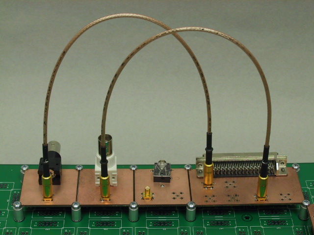
Like the 241 breadboard, it has a variety of
connector modules
to interface between circuits on the breadboard and
external systems such as test equipment.
However, instead of making the connections with pieces of
unshielded wire,
we will use
coaxial cable jumpers.
The small, gold cylinders
on the ends of the cables in the photograph
are SMB type connectors.
SMB connectors are push-on, so no rotation is required, just a
strong push or pull.

|
Warning
Because of their small size, SMB connectors are somewhat delicate.
When inserting or removing an SMB connector be sure that the two axes are
aligned and parallel, and that you apply force only in an axial direction.
Any rocking or sideways force may damage the connector.
Also, be sure to grasp the connector by the lower portion.
If you pull on the upper part of the connector, it will come apart.
|
This Week's Circuit
In the coming weeks we will build a variety of different modules
that will plug into this breadboard system.
Most of these will require a microcontroller to make them go,
so that's the obvious choice for our first module.
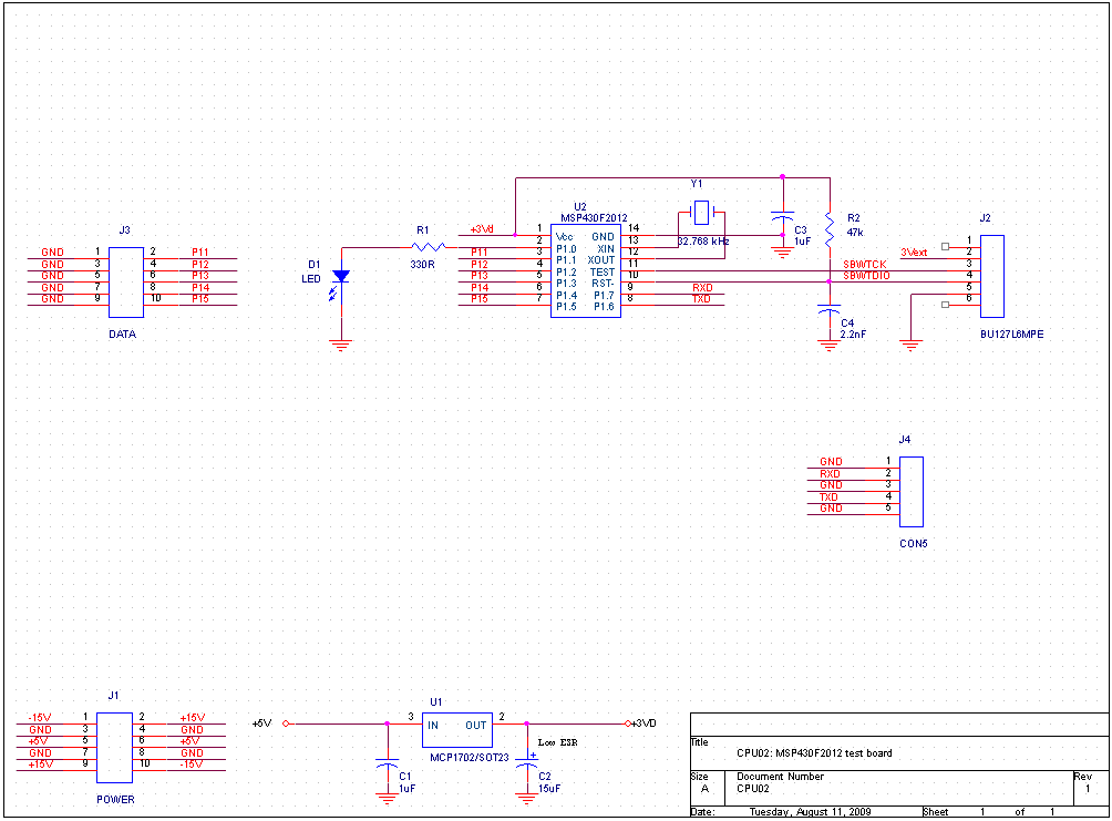
Here's the diagram for this week's circuit:
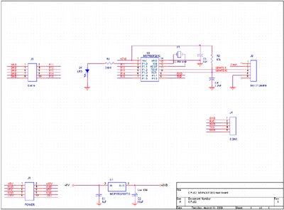
(Click to enlarge)
It looks a lot like the eZ430 kit module that you used in ELEC 220,
but has a lot more connectors.
This makes it
easier to incorporate into the various projects
we have lined up for it.
The pins of the MSP430 have been divided into
several different groups of functions, each with a supporting
component or connector.
Clockwise from the top of the chip they are:
- Pins 1 and 14: Power.
-
Supported by regulator U1, filter capacitors C1 and C2,
and bypass capacitor C3.
- Pins 12 and 13: Crystal.
-
We won't
use it
this week, but if we need an accurate frequency
reference in a future exercise, we can install a 32.768 kHz crystal
as Y1.
- Pins 10 and 11: Debug Interface.
-
This branch of the MSP430 family uses the Spy Bi-Wire two-wire
debugging interface which is supported by the USB dongle in the
eZ430 kit.
This is how we will download and debug programs on our microcontroller
modules.
These signals are connected to J2.
- Pins 8 and 8: Serial Interface.
-
The 2012 supports the I2C and SPI serial interface standards
in hardware.
Other family members have also have a UART function, but the 2012 doesn't,
so we will have to implement this in software.
These signals are connected to J4.
- Pins 3-7: Analog and Digital Inputs and Outputs.
-
This will be the interface to most of the other modules
we wish to control.
These signals are connected to J3.
- Pin 2: The LED.
-
It's always nice to have an LED that you can turn on and off to let
you know that things are OK.