(Click to enlarge)
In addition to their role as ordinary digital port pins, P1.6 and P1.7 are also connected to the USI (Universal Serial Interface) module. This module supports I2C and SPI protocols for communication with peripheral chips, but not the asynchronous protocol used for serial I/O with a computer. However, we can implement this protocol in software, using these same two pins in their digital port role. These two pins are connected to J2, the connector on the right hand side of the CPU board.
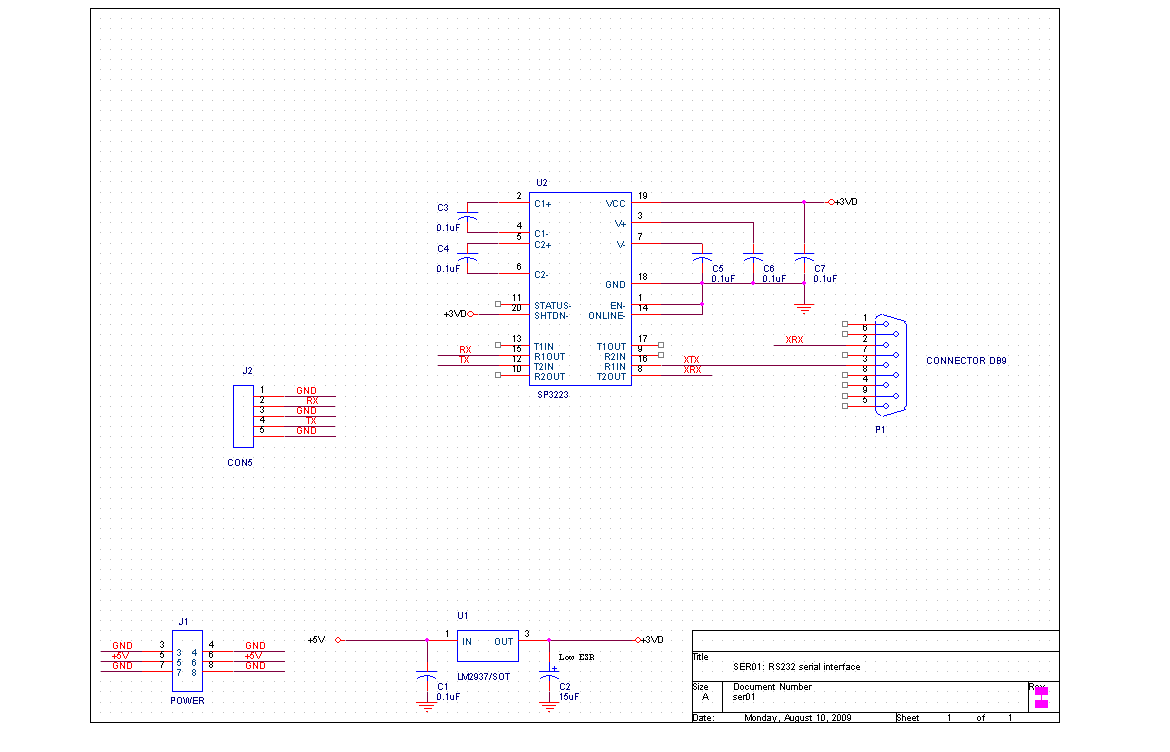
The RS232 serial port of the PC uses voltages of +5 V and -5 V to represent 1 and 0. These need to be converted to the +3 V and 0 V levels used by the MSP432. Fortunately, there are a number of chips available which will do this with a minumum of fuss. We'll use the SP3223, as shown in the following circuit:
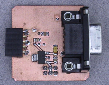
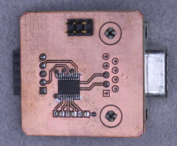
When assembled into a module for our ELEC332 breadboard, it looks like this:
|
| |||
Connect the modules. |
As mentioned above, the 5-pin connector on the right hand side of the CPU module plugs into the 5-pin connector on the left hand edge of this module. We will want to use the coax cable adapter to access the remaining I/O pins, so when everything is connected, it will look like this: 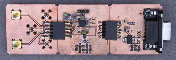
(Click to enlarge)
| ||
Connect to the PC serial port. |
Once you have the modules plugged together and
firmly attached to
the breadboard,
connect a cable from the serial port of the PC to the 9-pin connector
on the serial interface module.
| ||
Start and configure the Hyperterminal program. |
We eventually want to use this connection to allow programs on the PC
to interact with programs on the MSP430.
For now, we'll do this interaction manually, using the
hyperterminal
program on the PC
(All Programs->Accessories->Communications->HyperTerminal).
It will ask you a bunch of questions about location,
which you can ignore.
| ||
Configure the terminal program. |
Select
File->Properties
from the menu and choose the "Connect To" tab.
In the
"Connect using:" field, choose
COM1,
then click the "Configure..." button.
On the "Port Settings" tab, select
|
|
| ||
Build and load the program. |
Plug the USB debug interface into the CPU module,
start up IAR Embedded Workbench, and open the
lab3 workspace from this week's
zip
file.
Build, download, and run the
sio1
project.
| |
Activate Hyperterminal. |
With the cursor over the Hyperterminal window, hit <Enter> on the PC keyboard.
This will open the Hyperterminal connection.
If all is well, you should see
the alphabet
repeatedly
appear on the terminal screen.
The Hyperterminal program is a bit finicky about what it chooses to display and when it chooses to display it. Nothing will happen until it is connected, so be sure the box in the lower left corner of the window says "Connected" not "Disconnected." If it doesn't, try hitting <Enter> with the cursor in the window. The third box should say "9600 8-N-1". If not, bring up the configuration panel and make the necessary changes. Sometimes starting Hyperterminal and the MSP430 in a different order helps, as does hitting <Return> once both are running.
If in spite of your best efforts, nothing happens, check to be sure you
are in fact generating an appropriate signal.
Carefully probe the
tx
data line with the scope and verify that a signal
with levels of about +5 V and -5 V is present.
The signal on the
tx
data line is also put out on P1.2.
Use the connector modules you used last week
to connect this signal to the scope
and verify that it looks as it should.
The width of the pulses should be multiples of 1/9600 sec,
or roughly 0.1 ms.
| |
Programming Challenge. |
Even though it's happening really fast, typing the alphabet is not a very satisfying accomplishment for the amount of hardware we have assembled (and as we learned in 241, since the alphabet is a known quantity, sending it conveys no information). More impressive would be to send information that the MSP430 has gathered from the system in which it is embedded. So our first challenge is to build a digital voltmeter. Details are given in the Design Challenge section. |
|
| ||
Build and load the program. |
Select the
sio2
project from the lab3 workspace.
This program reads a character and places its least significant bits
on the P1 output port.
Build, download, and run the program.
| |
Send characters from PC to MSP430. |
With the cursor over the window of the Hyperterminal program,
type a character on the keyboard.
With the scope, probe the P1 output pins and verify that they have
the correct values for the least significant 5 bits of the character
you have typed.
A quick test is to type sequential digits.
The LED should come on for odd values and go off for even values.
| |
Programming Challenge. |
Again, probing around with the scope to find out the bits of a transmitted character is not a very effective use of our fancy hardware. We want to be able to send data from the PC to the MSP430 and thence to a system we wish to control. In the coming weeks we'll be doing exactly that, controlling motors in response to commands from the PC. As hinted last week, we'll be using PWM to do it, so let's get some practice. Your challenge is to write a program which reads a number from the PC and produces a PWM waveform with the appropriate duty cycle. Again, details are in the Design Challenge section. |