ELEC 332
Background
As with the previous exercise, we have two new circuit modules this week,
one prefabricated and one which you will fabricate.
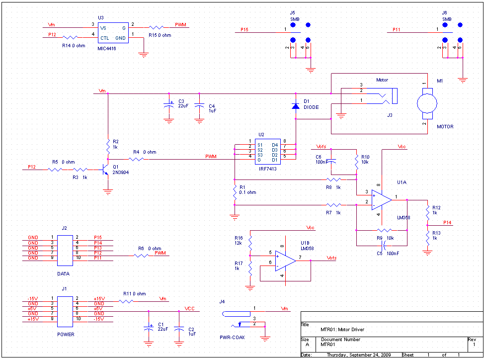
The prefabricated circuit is a PWM motor driver using a power MOSFET
as the switchiing element:
(Click to enlarge)
Like the op amp circuit board in Exercise 1, this circuit has a number of options.
However, instead of selecting them by removing and installing the components involved,
this circuit is configured by adding or removing 0 Ω resistors which are
used as jumpers.
The options that may be selected are:
- Power supply.
-
With R11 installed, the +15 V supply from the breadboard is selected.
With R11 removed, an external power supply, connected to J4, is used.
- MOSFET driver.
-
Three options are available for driving the gate of the power MOSFET, U2.
With R6 installed, it is driven directly from the output pin of the MSP430.
With R4 and R5 installed, a BJT is used to increase the high level drive voltage.
Finally, with R14 and R15 installed, a commercial MOSFET driver is used.
- Motor.
-
It is possible to drive either an external motor, connected via J3, or a motor
directly attached to the board. No jumpers are involved, the components involved
are robust enough to tolerate unsoldering and resoldering.