(Click to enlarge)
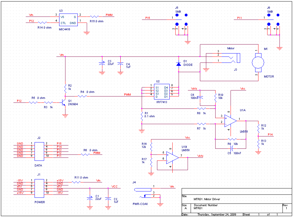
Our motor speed controller is built upon the PWM software we developed in Exercise 2. Since the output current of the MSP430 is too small to drive a motor, we will need a switching device to boost its output. In addition to providing more current, we can also utilize a higher voltage, so we can drive loads requiring significant amounts of power. The switching device we will use is a power MOSFET, as shown in the following circuit:
|
| ||
Set the power supply voltage. |
The motor we will be using is rated for a nominal voltage of 4.5 V,
so running it at 15 V is probably not a good idea.
A certain amount of voltage beyond the nominal value is acceptable, so set
the 15 V power supply voltage to 7.5 V.
| |
Connect the modules. |
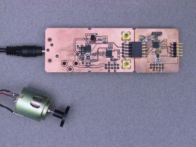
Plug the motor driver board into the 10-pin connector on the left hand side of the
CPU module. Plug the motor into the phone jack on the left hand side of the
motor driver board.
Plug this assembly into the breadboard.
(Click to enlarge) | |
Connect the scope and potentiometer. |
The two SMB connectors on the motor driver module provide access to
some of the pins on the MSP430.
The upper connector, J6, is connected to P1.1, which we will use to signal
the state of the program when it is running. Connect this to one of the channels
of the scope.
The lower connector, J5, is connected to P1.5.
We will use this as the analog input to specify the desired motor speed, so connect
it to the potentiometer as you did in Exercise 2.
Turn the potentiometer fully counter-clockwise, to avoid surprises when
the program starts.
| |
Build and load the program. |
Compile and load the program mtr1.c from this week's
zip file.
(Just the programs this week, you'll have to build your own workspace and projects.)
| |
Fire it up. |
Start the program and slowly turn the potentiometer clockwise until the motor
begins to turn. Turn some more and the speed should increase.
| |
Look at the signals. |
Using the 10x probe with the oscilloscope, measure the signals on the gate and drain of U2. Be extremely careful when probing that you do not cause a short. This is expecially easy with the milled circuit boards because of the narrow gap between the pins and the left over copper (which will usually be grounded). Record the waveforms that you observe. |
The ability to measure the current which is flowing in the motor has several potential uses:
The motor driver includes the ability to sense the driver current and to deliver a proportional signal to the A/D converter on the MSP430 via P1.4. Rather than do any of the useful things mentioned above, we will merely send the measured value to the D/A converter output for monitoring. This will prove that we can indeed measure the current if we ever have the need to do so.
|
| ||
Connect the Modules. |
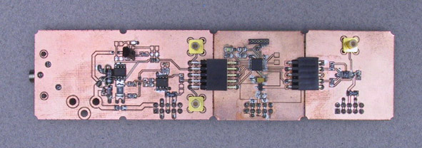
We will use the same setup as in the previous Part, with the addition of the
I2C DAC you built last week.
(Click to enlarge) | |
Build and load the program. |
The program mtr2.c from the
zip file.
has additional code to read the analog signal on P1.4 and
send it to the D/A converter.
| |
Try it out. |
Connect the D/A converter output to the scope or DMM (or both).
Start the program, adjust the speed, apply a load torque with your finger
or other means, and observe the variations in the current.
| |
Measure it. |
Set the motor speed at about mid range. Measure and record the voltage waveform across R1 and on pin 1 of U1. |