Spice is a circuit simulation program originally written at UC Berkeley in the 1970s. Pspice is one of the many modern day implementations of Spice which offers extended modelling capabilites, along with a graphical user interface for circuit entry and output display. The core Spice simulator works from a text file description of the circuit (called a spice deck since it was originally entered in the form of a deck of punched cards). For basic simulations (operating point, transient response, and frequency response) the user interface will shield us from these messy details.
Since the input to Pspice is the Cadence Capture program, we already know how to enter a circuit to be simulated. The only significant difference is that we need to check the "Analog or Mixed A/D" box rather than "Schematic" when creating a new project. A couple more tricks are required to run the simulation once we've entered the circuit. These will be revealed in the next section.
This exercise will cover the basics of time and frequency domain simulation. The full set of capabilities of Pspice are covered in the Cadence documentation, primarily the Pspice User's Guide and Pspice A/D Reference Guide. Since these comprise over 1200 pages between them, you might want to try one of the shorter Pspice tutorials that are available on the web. One good one is:
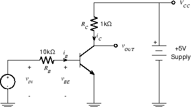
Recall the lowly common emitter transistor circuit from ELEC 242:
Depending on how we configure and operate the circuit it can serve either as a linear amplifier or a logic inverter. When used as a logic element, the output voltage depends on the supply voltage and the input threshold depends only on the forward voltage of the base-emitter junction. This means we can use it as a level shifter by simply connecting VCC to the power supply of the destination component. At least we can for low speed systems.
The simple transistor model we used in 242 leaves out a lot of aspects of real transistor behavior. For the simple, low frequency circuits of 242, it was adequate, But if we try to use it in a high speed digital circuit without considering these, we'll have problems.
Recall that we tried to use a transistor buffer as a level shifter in Exercise 4, to interface between the MSP430 and the IRF7413 MOSFET. Although the drive voltage was indeed increased, the high gate capacitance of the MOSFET (about 1000 pF) resulted in unacceptably high rise times. We could fix this by reducing the value of RC, at the cost of increased power dissipation.
In Exercise 8 we use transistor buffers to interface between the MSP430 and the AD9851, running at 5 V. The input capacitance for the AD9851 is much lower than the IRF7413, about 5 pF. In combination with a 1 kΩ collector resistor this gives a time constant of 5 ns, so the rise time should be satisfactory. However, if we were to build the above circuit, using a 2N3904 for the transistor, the performance would be unacceptable.
The primary reason for this is a phenomenon we didn't even talk about in 242: charge storage in the base. When a BJT is saturated, an excess of minority carriers accumulates in the base. When vIN goes to zero, these must be removed, either through RB or via recombination, before the transistor stops conducting. This results not only in a much larger rise time, but a significant delay before the transistor even begins to turn off.
There are a number of ways of dealing with this problem, including the one chosen for the circuit of Exercise 8: placing a small capacitor in parallel with RB. This raises the question: How do we choose the value of the capacitor? There are several possibilities: