(Click to enlarge)
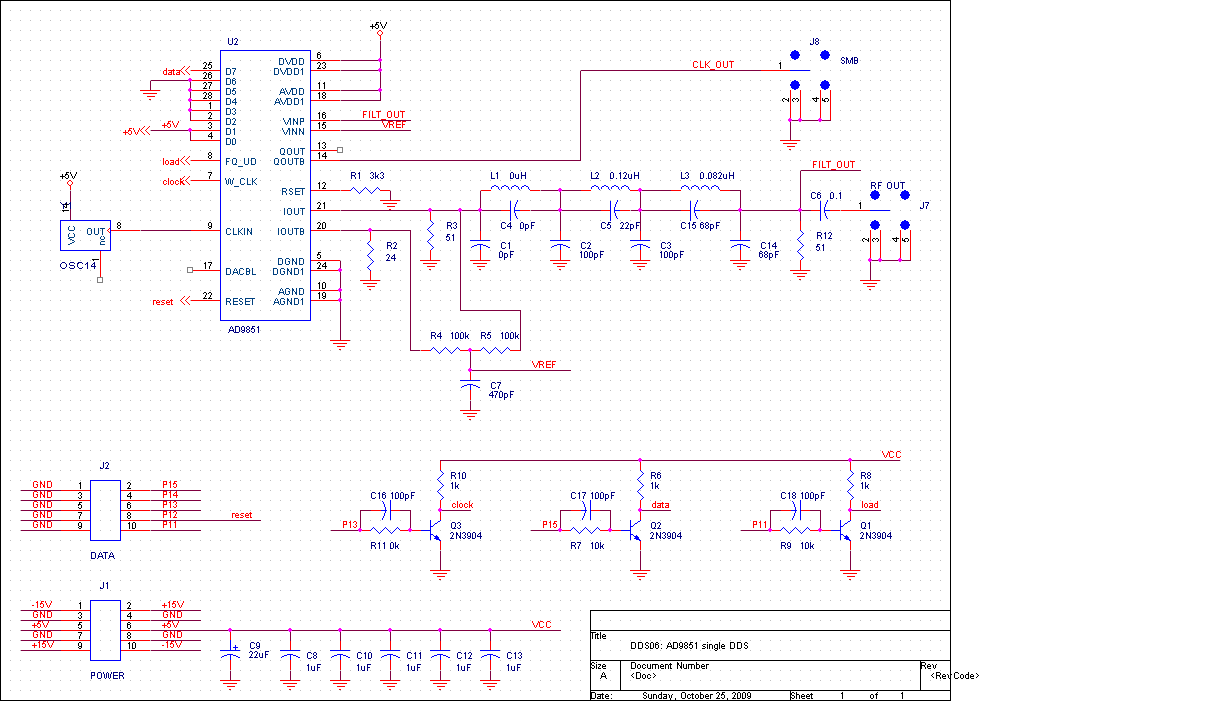
Like many of the chips we've used this semester, the AD9851 isn't very useful without a microprocessor to control it. Another similarity is that once we have added the microprocessor, very few additional components are required to get it to do useful work.
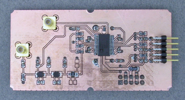
When laid out and assembled, it looks like this:
|
| ||
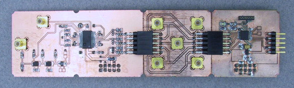
Connect the modules |
Since we will need to connect the CPU to an analog input as well as to the
DDS, we will place the feed-through SMB tap module from Exercise 6
between the CPU and the DDS.
This will also make it easier
to monitor the signals between the MSP430 and AD9851.
(Click to enlarge) | |
Connect the scope. |
Using the SMB connectors on the intermediate module,
connect channel 1 of the scope to the transmitter drive signal on P1.4
(the connector in the lower left corner).
Connect channel 2 to the
clock
signal.
Set the scope to trigger on channel 1.
| |
Build, load, and run the program. |
Compile, load, and run the program tone.c from this week's
zip file.
The green LED on the CPU board should come on.
| |
Look at the signals. |
Set the time time base to
display a full cycle of the
load
signal.
During this interval
you should see 40 pulses on the
clock
signal, one for each bit of the programming word.
Move channel 2 to
the
data
signal and observe the sequence of data bits.
Move channel 2 to the RF OUT connector on the lefthand edge of the DDS module. Adjust the vertical scale as necessary. You should see a 1 MHz sine wave.
Set the vertical scale to 2V/div and connect channel 2
to the
CLK_OUT
signal on the top edge of the DDS module
You should see a 1 MHz square wave.
| |
Change the frequency |
Find the line in tone.c where the operating frequency is set
and change it to a different value (less than 40 MHz).
Build and load the program and verify that you do indeed have a new frequency.
Set the frequency to a value between 30 and 40 MHz. Using the 10x probe and an appropriate vertical gain, carefully probe the DAC output of the AD9851. The safest place to do this is at the input to the filter. Note the distinctive stairstep appearance of a D/A output signal. Move the probe to the output of the filter and note the extent to which these steps have been removed. |
|
| ||
Connect some more modules |
Mount the potentiometer module that we used in the PWM and motor driver
labs in a convenient location on the breadboard.
Connect its output to P14 via the intermediate connector module.
Reconnect channel 2 of the scope to the
RF OUT
connector on the DDS.
| |
Load another program |
Compile, load, and run the program vco.c,
included in the
lab8.zip
file.
| |
Look at some more signals |
Observe the DDS output and note how its frequency changes as the potentiometer knob is turned. |
If we were to replace the potentiometer in the previous Part with a microphone and change the frequency from 1 MHz to an appropriate value in the FM broadcast band, we would have our own FM radio station. Unfortunately, the sample rate of the AD9851 is too low to reach the FM band. However the square wave output of our DDS module is rich in odd harmonics, so if we set the AD9851 to an odd submultiple of the desired frequency we can reach the FM band. Since we're also broadcasting on all of the other harmonics, this won't do for a commercial product, but as a quick experiment we can probably get away with it.
|
| ||
Reconnect the modules |
Set the function generator to produce a 1 kHz sine wave.
Adjust the amplitude and offset controls for a 2 V p-p amplitude
and a 1 offset, i.e. peak values of 0 and 2 V. This will put the
signal comfortably in the range of the MSP430 A/D converter.
Disconnect P14 from the potentiometer and connect it to the function generator output.
Mount one of the antenna modules from last week's exercise to the breadboard and
connect the
CLK_OUT
signal of the DDS to it.
| |
Rebuild the program |
The range of our DDS isn't quite high enough to utilize the 3rd harmonic, but the
5th is comfortably within its range. Set the frequency in the vco.c program
to 88/5 MHz and rebuild the program.
| |
Get on the air |
Tune the Kaito radio to 88.0 in the FM band. You should hear a 1 kHz tone. To insure that our system is indeed the source, vary the function generator output and verify that the received tone changes as well. Since the Kaito radio is portable, investigate how far away our signal can be received. |