(Click to enlarge)
(Click to enlarge)
(Click to enlarge)
(Click to enlarge)
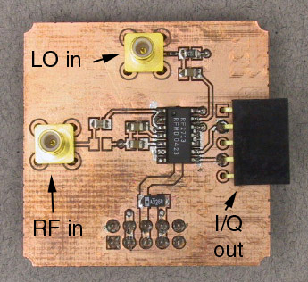
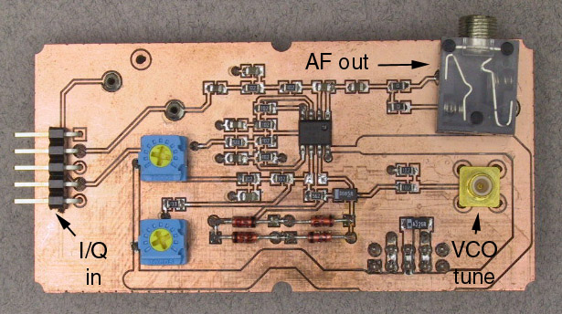
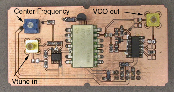
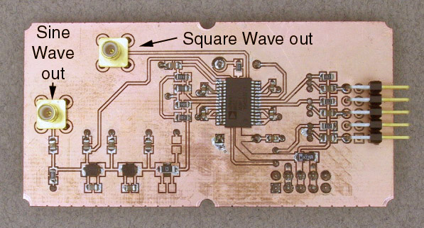
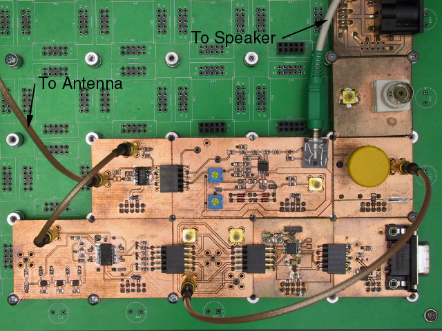
We have several new modules for this week. These were described in the Background section, but for convenient reference, here are their pictures, including labels for the connectors and adjustments.
|
| ||
Assemble the modules. |
Assemble the chain of modules that you used in the Design Challenge
for Exercise 8 (RS-232 -> CPU -> SMB feedthru -> DDS).
Connect the 5-pin connector on the I/Q mixer to the 5-pin connector on the
filter module and plug both into a convenient location on the breadboard.
Connect the square wave output of the DDS to the LO input of the mixer.
Connect the AF output of the mixer to an amplified speaker.
(Click to enlarge) | |
Build and load a DDS tuning program. |
Modify the program you wrote for the Exercise 8 Design Challenge
as necessary so that it will produce frequencies between 1 MHz and 3 MHz
in multiples of 20 kHz.
When divided by two in the RF2713, these will be the carrier frequencies
for the AM broadcast band.
Compile, load, and run your program.
Connect the oscilloscope to the square wave output of the DDS and verify
that it is producing the correct frequencies.
| |
Test with the signal generator. |
Set the signal generator to produce a 1 MHz
output
at a -50 dBm output level.
Set the modulation to AM, 400 Hz.
Connect the signal generator output to the RF input of the mixer.
Turn the volume of the speaker all the way down.
Turn everyting on. Start your DDS program and set the output frequency to 2 MHz (for a received carrier frequency of 1 MHz after the division by 2). Slowly increase the volume of the speaker. You should hear a 400 Hz tone. Examine the AF output with the scope. You should see a 400 Hz sine wave. Turn off the modulation, but leave the signal generator output on. The output should disappear (from both the speaker and the scope). However, if the signal generator and DDS are not at exactly the same frequency, there will be a beat note at the difference between the carrier and local oscillator frequencies. Adjust the fine tuning knob on the DDS (or the signal generator frequency if your DDS software does not support fine tuning) until this frequency is as close to zero as you can make it.
Turn the modulation back on.
If there was a significant difference between the carrier and LO frequencies,
your tone should now be much purer.
| |
Characterize real world signals. |
With the signal generator as in input,
it's easy to get sufficient amplitude and
there are no other interfering signals
to cause problems.
If we replace the signal generator with an antenna, things aren't so nice.
Connect the external antenna to the input of the spectrum analyzer.
Set the center frequency to 1 MHz and the span to 1 MHz.
This will display the spectrum of the AM broadcast band.
You should see a number of peaks, each located at a multiple of 10 kHz.
Adjust the level and bandwidth as necessary to get a good display.
Note the frequencies of several of the strongest stations.
| |
Test with real world signals. |
Disconnect the signal generator from the RF input to the mixer and
replace it with the outside antenna.
Try tuning your DDS to some of the frequencies noted in the previous step
(be sure to remember the factor of 2).
You should be able to receive one or two stations,
but there will probably be a lot of noise and distortion.
Although the linear theory predicts that we should be able to reject
interfering stations (they will be removed by the low pass filter),
the nonlinearity of the actual mixer results in significant intermodulation
among the competing signals.
| |
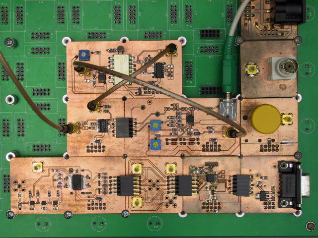
Add bandpass filter. |
We can fix this problem by placing a bandbass filter between the antenna
and the mixer.
(Click to enlarge) |
|
| ||
Assemble the modules. |
Leave the I/Q mixer and filter modules connected together as in Part 1.
Plug the VCO module into a convenient location on the breadboard and connect
its VCO output to the LO input of the mixer.
Connect the Vtune input of the VCO to the VCO tune output of the filter module.
This replaces the DDS with the VCO as the LO and closes the loop via the
quadrature output of the mixer.
(Click to enlarge) | |
Test with the signal generator. |
Connect the RF input of the mixer to the output of the signal generator.
Set the signal generator as in Part 1, but reduce the frequency to 800 kHz.
(The limited tuning range of the VFO won't allow us to reliably reach 1 MHz.)
Turn everything on and adjust the Center Frequency pot on the VCO module
until the VCO output frequency is 1600 kHZ (2 x 800 kHz).
You can do this either by eye, by observiing the VCO output on the scope,
or by ear, by listening for the
zero beat
as the local oscillator frequency approaches the carrier frequency.
In either case, as you get close to the correct frequency, the feedback in the
loop should take over and pull the local oscillator frequency the rest of the way.
At this point, the local oscillator and carrier are phase locked together and you
have a coherent AM demodulator.
| |
Explore the limits of phase locking. |
Without changing the center frequency setting on the VCO, gradually increase the signal
generator frequency until the loop looses lock, then decrease it until lock is reestablished.
Note both frequencies.
Perform the same test by reducing the signal generator frequency.
The outer range of frequencies is called the
hold-in range
and the inner one the
pull-in
or
capture range.
If these are not symmetric about the nominal carrier frequency (800 kHz),
adjust the VCO center frequency until they are.
Reduce the signal generator output in steps of 10 dBm and repeat the above
measurements until the loop will no longer reliably remain locked.
| |
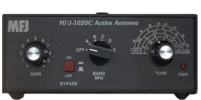
Test with real world signals. |
Disconnect the signal generator and connect the output of the MFJ-1020C to the RF input of the mixer (the antenna should still be connected to the input of the MFJ-1020C). Tune the MFJ-1020C and the VCO center frequency to receive as many different stations as you can within the VCO's tuning range. Compare the quality of reception with that of the incoherent demodulator. |