(Click to enlarge)
(Click to enlarge)
(Click to enlarge)
Since all of this week's hardware has already been built for you, there's not very much to do in the formal lab portion of this week's exercise. Our main goal here is to verify that everything works as it is supposed to, then move on to the centerpiece of this week's exercise, the design challenge.
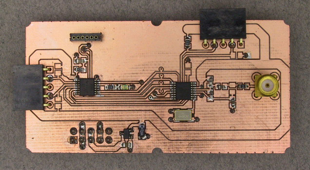
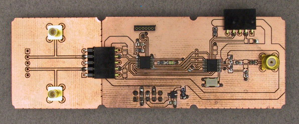
Our new components this week include two new modules and an accessory. Since a radio system requires both a transmitter and a receiver, we have at least two copies of each.
The easiest way to use our radio chip is as a direct FSK modulator/demodulator. I.e. we put a binary signal into the transmitter and the same signal comes out of the receiver. We could use this to transmit digital data, e.g. by using the SIO data stream from Exercise 3. Or we could transmit PWM encoded analog data such as the motor control signal from Exercise 4. Or we could transmit timing information such as the sonar pulse from Exercise 6. Or we could just send a square wave from the function generator.
|
| ||
Assemble the modules. |
Since
the main point of wireless communication is to transmit information
between two widely separated points,
we will eventually want to put the transmitter on one breadboard
and the receiver on the other.
However, initial program download and checkout is easier with both
the transmitter and receiver modules on the same bench.
The easiest way to achieve this is to put the transmitter in one corner
and the receiver in the other corner of the same breadboard.
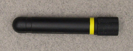
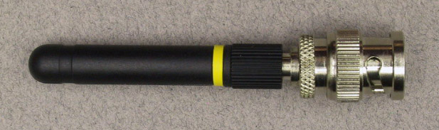
Connect one of the antennas to the SMA connector on the transmitter. 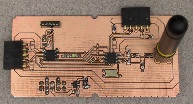
(Click to enlarge) 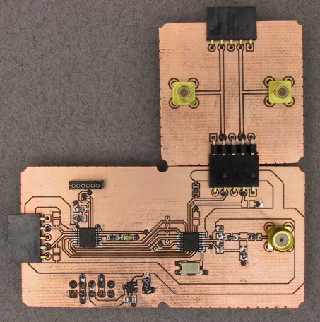
(Click to enlarge) 
(Click to enlarge)
Connect a 10x probe to channel 1 of the scope.
Connect J4-4 of the receiver (the left hand SMB connector) to channel 2.
| |
Set up the spectrum analyzer and function generator. |
With the help of a SMB to BNC adapter, install one of the antennas
on the input of the spectrum analyzer.
(Click to enlarge)
Set up the
function generator
to produce a 1 kHz square wave.
Adjust the amplitude and offset so that the low value is
0 V and the high value is 3.3 V.
Using one of the 5-pin SMB feedthru modules, connect
this signal to J4-4 on the transmitter module
(second pin from the left on the top right connector).
| |
Build, load, and run the transmitter program. |
With the debugging interface connected to the transmitter module,
compile, load, and run the program fsk_xmit.c from this week's
zip file.
The green LED on the CPU board should come on.
You should be able to see the transmitted signal on the spectrum analyzer.
If necessary, adjust the spectrum analyzer for a satisfactory display.
Change the frequency of the square wave and observe how the spectrum changes.
| |
Build, load, and run the receiver program. |
Move the debug interface to the receiver module. Compile, load, and run the program fsk_recv.c. You should be able to see the received signal on channel 2 of the scope. What is the maximum frequency square wave that can be reliably transmitted? |
If we want to send data, rather than timing information, the radio chip includes hardware to simplify and speed up that task. Rather than an asynchronous protocol like we used in Exercise 3, it uses a synchronous protocol with the data assembled into packets. Although the packets can be of any size, our example code transmits just a single data character per packet. Additional bits are required for bit and word synchronization.
|
| ||
Assemble the modules. |
On the transmitter, move the 5-pin SMB feedthru from J4 to J3.
(Click to enlarge) 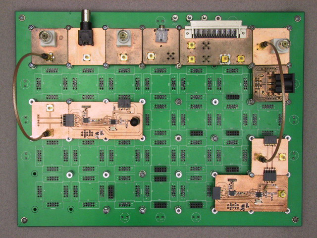
(Click to enlarge) | |
Build, load, and run the transmitter program. |
Move the debug interface back to the transmitter module.
Compile, load, and run the program pkt_xmit.c.
This program will transmit a single byte packet with the value of
the byte increasing by one with each transmission.
For now, do not reprogram the receiver.
Adjust the scope for a stable trigger from the external input.
Adjust the timebase to display a single received packet on channel 2.
You should be able to identify the preamble, sync word, data byte,
and trailer of the packet.
| |
Build, load, and run the receiver program. |
With the receiver in packet mode, we can no longer view the raw FSK
received signal.
Instead, a single pulse per received frame will appear on the pin
connected to channel 2.
You can either leave this connected and use channel 1 to monitor the more
interesting receiver output, or you can move the SMB feedthru to J3.
(Click to enlarge) |