Soldering a board which has been milled on the T-Tech is a bit more complicated than soldering a commercially fabricated board.
- The vias are not plated through and must be manually connected from top to bottom.
- The pads are not pre-tinned so the bare copper must be cleaned before soldering, and a more liberal use of flux is required.
- The bulk of the unused copper is left on the board, rather than being etched away. This makes it easier to cause a short when too much solder is used on a pad.
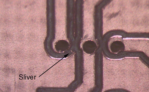 Because copper is a very ductile material, it is possible to leave thin slivers
which are still attached to the remaining metal. This is especially common at
acute angled corners, as shown in the photo.
Examine the board carefully before beginning work and remove any such slivers
with the knife or tweezers.
It is important to remove these before they can cause trouble, because they can
be very difficult to find once they have been covered with flux.
Because copper is a very ductile material, it is possible to leave thin slivers
which are still attached to the remaining metal. This is especially common at
acute angled corners, as shown in the photo.
Examine the board carefully before beginning work and remove any such slivers
with the knife or tweezers.
It is important to remove these before they can cause trouble, because they can
be very difficult to find once they have been covered with flux.
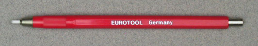
The most convenient way to clean the pad is with the glass fiber brush. Scrub the pad with a few firm strokes and, voila, bright, shiny copper. For best results the fibers should protrude about 2-3 mm from the tip of the handle. When you run out of fibers, there are refills in the drawer.
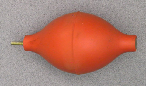
Since the glass is brittle, little bits will break off and be left behind on the otherwise clean joint. These should be removed with the blower bulb. Resist the temptation to wipe them off with your finger tip, as this will leave fingerprints on the board and glass fibers in your fingertip. Since they are transparent and tiny, they will be difficult to remove.
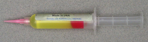
For each such via, clean and flux the area adjacent to the hole on both sides of the board as described above. Place the board in the vise with the ground plane side up. Using the spool of 28 ga. bare wire, insert the end of the wire so that about 5 to 10 mm protrudes from the opposite side of the board. Solder the wire and clip it flush with the board. Clip about 2 mm from the end of the wire on the spool (to remove the bump of solder) and repeat until all vias are filled. Turn the board over and solder and clip all of the protruding wires on the other side.