ELEC 332

PCB Supplies and Materials

Preparing a Blank Board

The blank PC board material is held in place by two dowel pins which fit into tooling holes drilled in the board. For the standard 6" x 6" blank board, the holes should be in the locations shown in the drawing. If you have a blank board with the tooling holes already drilled, skip to the next step. If no pre-drilled boards are available, you can prepare one using the following procedure.

Note

The tooling holes must be drilled on the T-Tech machine. Do not try to drill them on a drill press or milling machine. This will result in holes which are improperly sized and positioned, and which have burrs that will keep the board from lying flat.
1. Cut a 6 by 6 inch blank
Raw board material is purchased in sheets of either 9 x 12 inches or 12 x 18 inches. A 9 x 12 board cannot be cut into 6 x 6 pieces without waste. A 12 x 18 board can be cut into six 6 x 6 pieces.
2. Position the blank on the milling machine
Mark the center of one of the 6 inch edges of the blank board with a pen. Temporarily remove the rear alignment pin and place it in the plastic box for safekeeping. The pin is difficult to remove by hand, so use a pair of pliers or the aligator clip in the plastic box. Place the board on the backing material with the lower edge in contact with the front alignment pin at the marked position. Align the board so its edge is parallel to the edge of the table and firmly tape down both edges.

(Click to enlarge)
3. Set the tool height
Set the tool height for drilling as described in the PCB Milling instructions.
4. Install a 1/8 inch drill
Mount a 1/8 inch drill bit in the spindle as described in the PCB Milling instructions.
5. Drill the lower hole
Bring up the Move dialog from the Mill menu. Enter "-50" in the X field and "0" in the Y field. Select Absolute and click OK. The tool will move to a position just above the lower edge of the board.

(Click to enlarge)
Bring up the Jog dialog from the Mill Menu. Click the Spindle On button. If this is the first time you have started the spindle from the jog dialog, it will accelerate to its maximum speed (100000 rpm), regardless of the setting of the Spindle Speed slider. Grab the slider bar and move it to a speed of approximately 20000 rpm. Note that it will not respond until the spindle motor start delay has timed out (as indicated by the spindle on/off button popping back up).

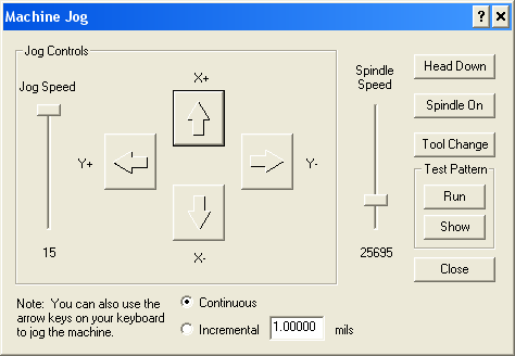
Once the spindle speed has stabilized, click the Head Down button, wait until the drill has completed its downward stroke, and click the Head Up button. Click the Spindle Off button, wait for it to stop, and click Close.


(Click to enlarge)
6. Drill the upper hole
Select Material Change from the Mill menu to move the head out of the way. Untape the board and place the hole that was just drilled over the front alignment pin. Rotate the board until its edge is parallel to the edge of the table and retape both edges. Repeat the process from the previous step, but enter "4200" into the X field of the Move dialog. Be sure to remember to select Absolute.
7. Replace the rear alignment pin