| |
1. |
|
Set up directory structure
|
| |
|
|
These instructions assume that you have set up a directory structure
as described in the
PCB Layout Tutorial.
A skeleton of this structure, along with
some
template files
is contained in the
pcb.zip
file.
If you have not set up this structure previously, you should
download and unpack this file before proceeding.
At this point you should have the following structure.
pcb
|-- blanks              ; outlines of the standard sized blank boards
|   |-- blank3x6.gbr
|   `-- blank9x6.gbr
|-- build_panel.exe     ; a program for combining multiple boards into a single panel
|-- example_board       ; the artwork and drill files used in these instructions
`-- your_board          ; your board would go here in the directory sturcture
There are other files and directories included in the zip file, but
these are the ones we will be using here.
It is assumed that the board you will be milling is in the
example_board
directory.
|
| |
2. |
|
Collect Artwork Files.
|
| |
|
|
If you have not already done so
generate the artwork and drill tape files for your board
as described in the
PCB Layout
tutorial.
The output of the PCB layout software is a set of files
describing the features (outline, traces, holes, etc.)
which comprise the board.
Traditionally the files describing the copper patterns or traces
are called artwork or Gerber files.
The files containing the hole sizes and locations are called
drill files.
For a basic two layer board, you will need three files:
one artwork file for each of the top and bottom layers
and a drill file. Each pcb layout program has a different
set of conventions for naming these files.
These instructions will assume they are named top.gbr,
bottom.gbr, and holes.drl.
|
| |
3. |
|
Verify Design Rules
|
| |
|
|
Boards suitable for basic milling have the following restrictions:
1. Traces and spaces must be at least 12 mils wide.
2. Large holes (>40 mils) may be of any size, but small holes
(<= 40 mils) must be one of the following sizes (in mils):
12, 16, 20, 25, 30, 36, 40.
These restrictions may be relaxed in the advanced milling processes
described elsewhere.
|
| |
4. |
|
Verify File Formats
|
| |
|
|
If you followed the instructions in the
PCB Layout Tutorial,
then your files will have the correct format, but the
artwork files will have the extension .art rather than .gbr.
If you have used a different layout process, you should verify
that your artwork files have the following format:
Units:
English
Digits:
Integer 5, Decimal 3
Mode:
Absolute
Leading zeros suppressed
Your drill files should have the same parameters, except that
the number of integer digits should be 2 instead of 5.
|
| |
5. |
|
Assemble Boards into a Panel
|
| |
|
|
If your board is a module for the ELEC 332 breadboard system,
or if you wish to fabricate several boards (or several copies
of the same board) in a single run, then you should create
a set of combined artwork files as described in
Combining Multiple Boards.
If not, proceed to the next step.
|
| |
1. |
|
Start IsoPro
|
| |
|
|
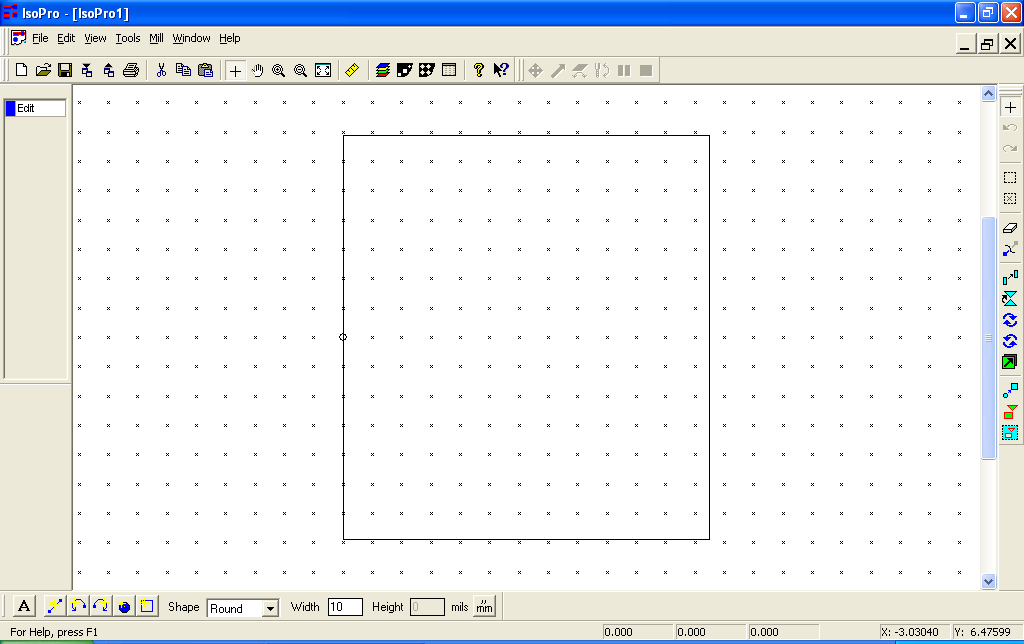
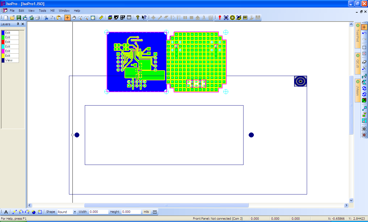
You should see a display like this.
The rectangle in the middle of the screen represents the working
area of the milling machine.
|
(Click to enlarge)
|
| |
2. |
|
Import Gerber files
|
| |
|
|
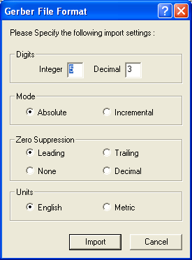
Select File->Import->Gerber File(s)... from the menu bar.
Browse to the directory where you
have placed your artwork files (e.g.
example_board
in the above directory sturcture).
Select
top.gbr and bottom.gbr,
and click
Open.
Accept the defaults and click
Import.
Hint:
If you select top.gbr first, then shift- or control-click to select
bottom.gbr, the top layer will be displayed on top of the bottom layer.
If you have a ground plane on the bottom layer, this will make it much
easier to see the top layer traces.
|
(Click to enlarge)
|
| |
3. |
|
Import drill file
|
| |
|
|
Select File->Import->Drill File(s)... from the menu bar.
Browse to your board directory,
select
holes.drl,
and click
Open.
Again, accept the defaults and click
Import.
|

(Click to enlarge)
|
| |
|
|
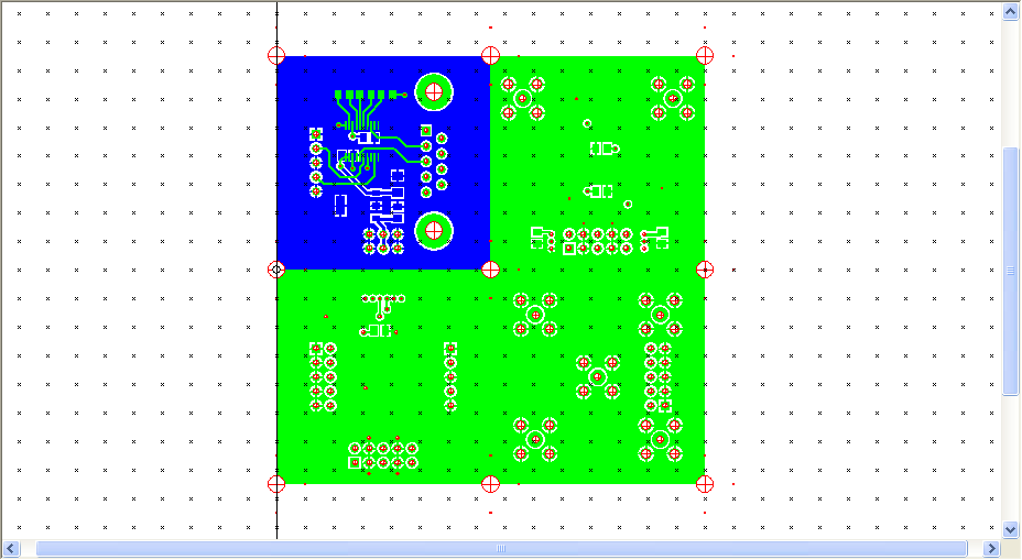
At this point your screen should look something like this.
|
(Click to enlarge)
|
| |
4. |
|
Examine your data
|
| |
|
|
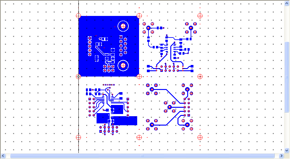
Carefully examine the top and bottom layers, the drill holes,
and their relationship to each other.
Verify that everything is present, the right size, and in the right
place.
Unlike the layers in Cadence Allegro, the layers in IsoPro are
not transparent.
To view the hidden layers, click on the entry in the
Layer Palette for the occluding layers
until their status changes from
view
to
hide.
Note:
After changing the status of a layer, no change takes place in the display until
the cursor is moved from the layer palette back in to the main window.
|
(Click to enlarge)
|
| |
5. |
|
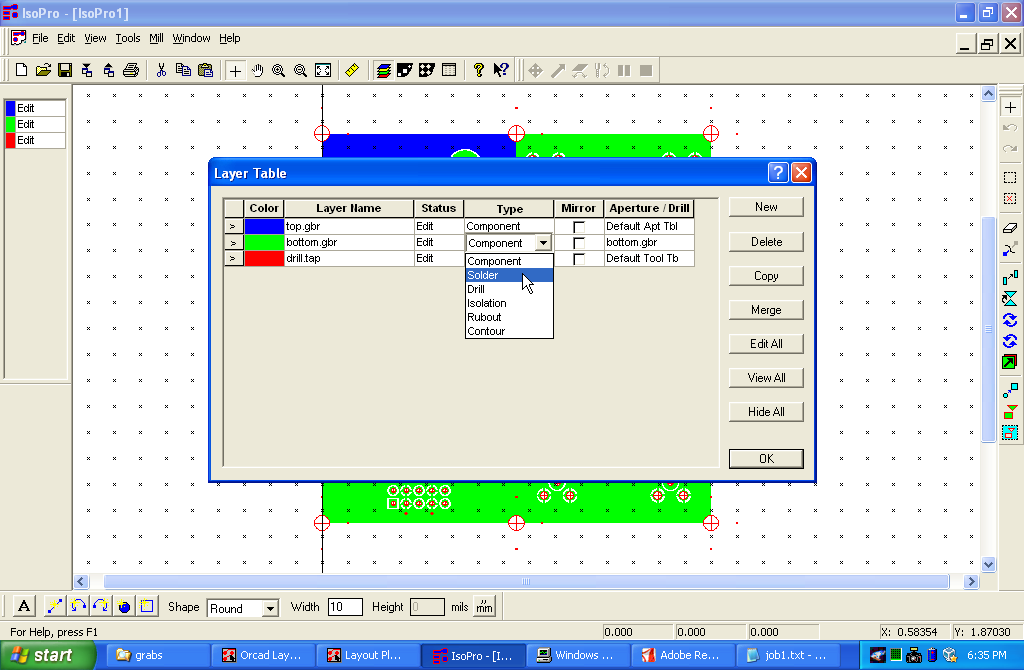
Set up the layer table
|
| |
|
|
It is necessary to tell IsoPro which is the bottom layer
so that it will know to mirror the tool motions.
Click on the
Layer Table button
( )
to bring up the layer table.
Click on the
Type
field for bottom.gbr and select
Solder
from the drop-down list that appears.
Do not check the mirror box.
It will be checked automatically in the next step. )
to bring up the layer table.
Click on the
Type
field for bottom.gbr and select
Solder
from the drop-down list that appears.
Do not check the mirror box.
It will be checked automatically in the next step.
|
(Click to enlarge)
|
| |
6. |
|
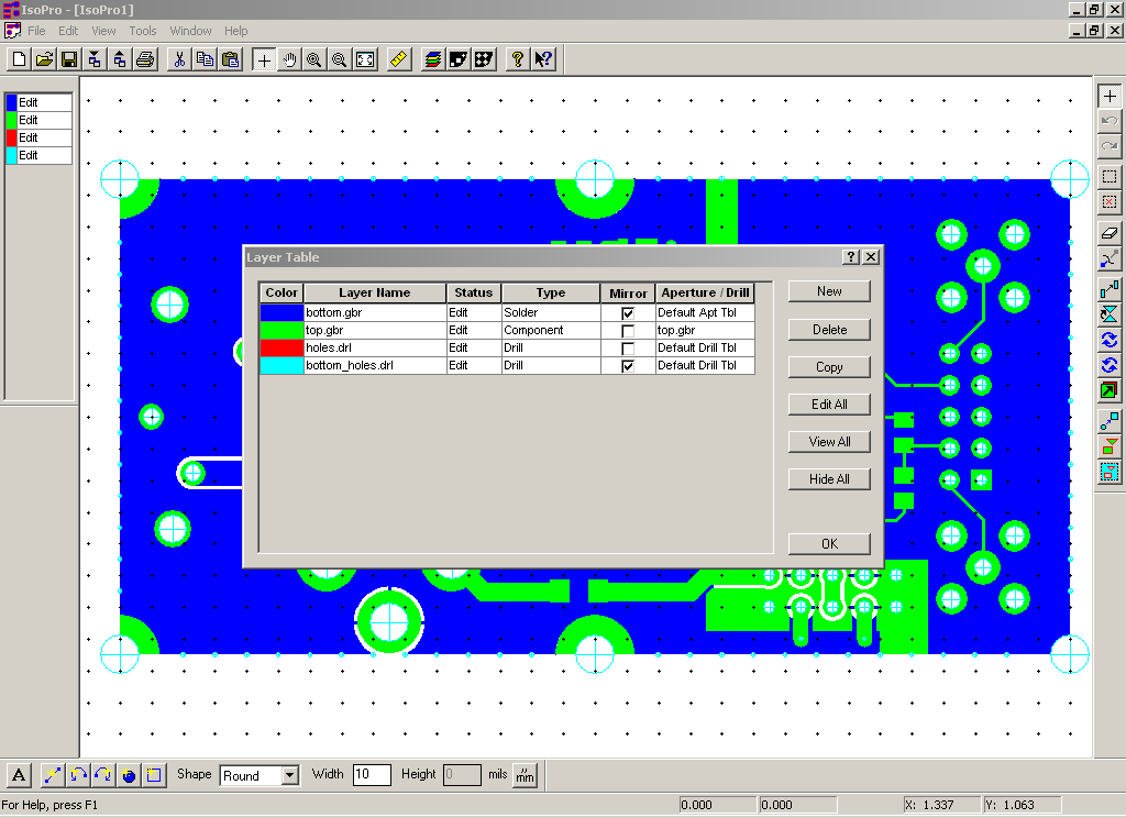
Create bottom drill layer
|
| |
|
|
Drilling completely through the board can create burrs on the back
side of the board and the surface of the backing material.
These burrs can prevent the board from seating firmly against the
backing material and cause the depth of the isolation cut to be uneven.
To prevent this, the drills are set to cut only halfway through the
board and are drilled from both sides.
Since the back side is mirrored, it is necessary to create a mirrored drill layer.
The layer table should still be displayed from the previous step,
if not, bring it back up.
Select the drill layer by clicking on the > symbol at the left end
of the drill layer row.
Click the
Copy
button on the right hand side of the dialog box.
This will create a new layer named "Copy of holes.drl".
If you like, change this to something more meaningful such as "bottom holes".
Check the
Mirror
box for this new layer.
Verify that both the bottom Gerber layer and the bottom holes
layer have their mirror boxes checked.
Close the layer table by clicking
OK.
|
(Click to enlarge)
|
| |
7. |
|
Run the isolator
|
| |
|
|
Select
Edit->Select...->All Data
from the menu bar.
Then select
Tools->Isolate from the menu bar or press the
Isolate button
( ).
In the
Isolate Layers
dialog box, enter "11" into the first line of the tool table.
Select top.gbr and bottom.gbr in the layers table.
Check the
Isolate selected only
box.
In the
Tool Type
field, select
Pointed Tool.
Finally, click the
Isolate
button.
When the isolation is complete,
select Edit->De Select...->All Data from the menu bar. ).
In the
Isolate Layers
dialog box, enter "11" into the first line of the tool table.
Select top.gbr and bottom.gbr in the layers table.
Check the
Isolate selected only
box.
In the
Tool Type
field, select
Pointed Tool.
Finally, click the
Isolate
button.
When the isolation is complete,
select Edit->De Select...->All Data from the menu bar.
|
| |
8. |
|
Examine the isolation
|
| |
|
|
Carefully examine both isolation layers, making sure there are
no gaps in the isolation.
If the spacing between two pads or traces is too small for the
tool to pass through, they will be left connected, creating a short.
If this happens, you will have to redo your layout to increase the spacing.
|
If you have used the build_panel program your board should already be
properly positioned. In this case you can skip to the next step:
Starting the T-Tech Machine.
If not, it will be necessary to position your board so that it properly
fits the blank material.
| |
1. |
|
Choose the appropriate sized blank
|
| |
|
|
Blank board material is available in the following sizes:
|
Blank Size
|
Maximum Board Size
|
|
6 x 3
|
4 x 1.5
|
|
6 x 4.5
|
4 x 3
|
|
6 x 6
|
4 x 4.5
|
|
6 x 9
|
4 x 7.5
|
|
9 x 12
|
7 x 10.5
|
You should choose the smallest blank which will accomodate your board.
|
| |
2. |
|
Load board outline
|
| |
|
|
Select File->Import->Gerber File(s)... from the menu bar.
Browse to the
blanks
directory and select the file corresponding
to the size of blank board you will be using.
E.g. if you are using a 3" x 6" blank,
select
blank3x6.gbr,
and click
Open.
Accept the defaults and click
Import.
|
(Click to enlarge)
|
| |
3. |
|
Immobilize the board outline
|
| |
|
|
If the layer palette is not visible (in the left-hand border of the main window),
click on
View
in the menu bar, then click on the
Layer Palette
entry at the bottom of the menu to enable it.
In the layer palette, click on the entry for the board outline to change the
status from
Edit
to
View.
|
| |
4. |
|
Move the board into the usable area of the blank.
|
| |
|
|
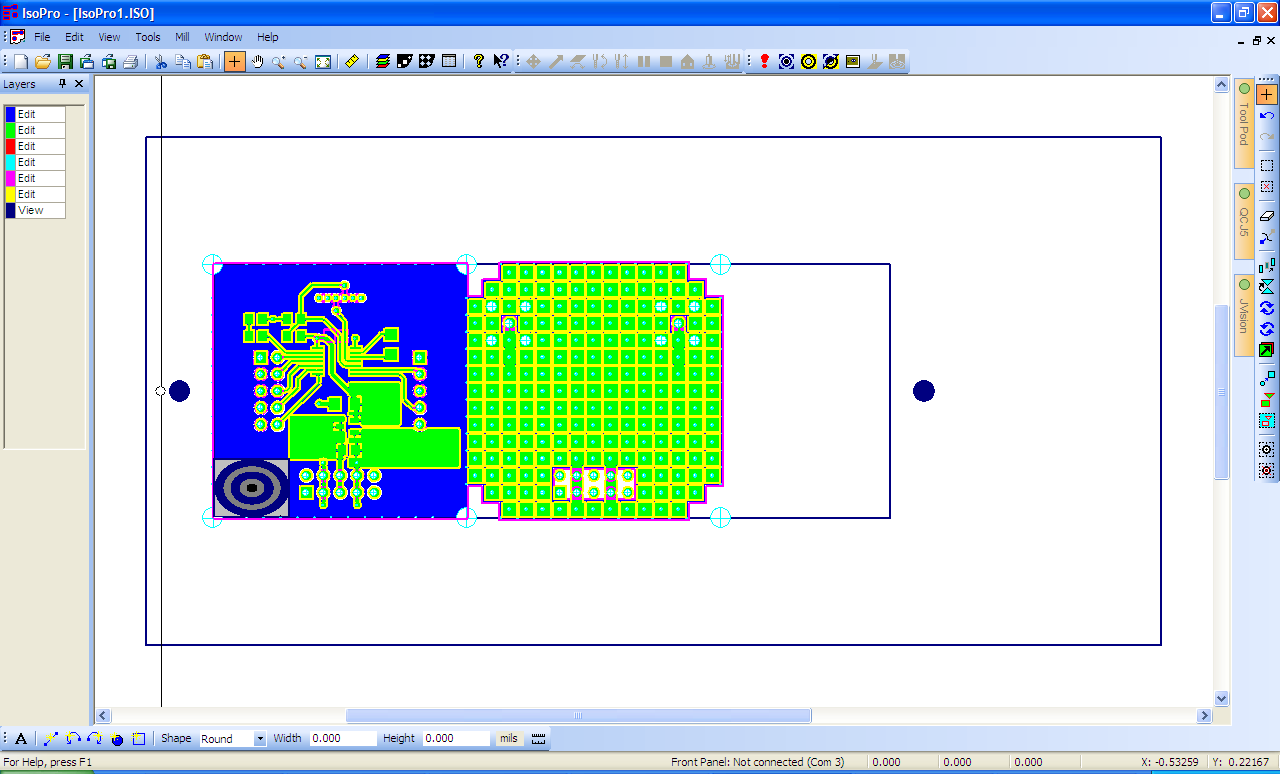
Select
Edit->Select...->All Data
from the menu bar.
Click on the interior of the board and drag until everything is inside
the interior rectangle of the board outline, which represents the
usable area of the blank.
Select Edit->De Select...->All Data from the menu bar.
|
(Click to enlarge)
|
| |
5. |
|
Save your work
|
| |
|
|
Select File->Save as ... from the menu bar.
Choose a meaningful name for your project, or simply accept the
default which will be something like IsoPro1.iso.
|
| |
2. |
|
Set the contact target area
|
| |
|
|
In order to control the depth of cut, the QCJ5 must know the z-axis location of
the tool tip.
This is determined by moving the tool over
an unused
area of the board and slowly moving it down until electrical contact is sensed
between the tool and the copper surface of the board.
To define the area where this test will be made
use the
Set target area
tool (Tools->ContactByTouch->Set target area).
Click and drag the tool across a small area (about 200 mils on a side)
in a region of your board which contains no traces or holes.
If your board is too dense to provide such an area, place it
immediately adjacent to the active area of the board in either the +y
or -y direction (left or right when facing the machine).
|
| |
3. |
|
Activate the vacuum holddown
|
| |
|
|
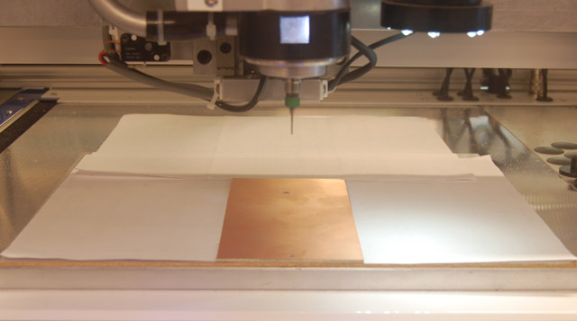
The board is held flat by vacuum,
supplied through the holes in the surface of the table
and backing material.
Cover all exposed holes with pieces of paper.
Start the vacuum by pressing the foot switch on the floor
next to the vacuum pump.
|
(Click to enlarge)
|
| |
4. |
|
Run the drill layer
|
| |
|
|
Select Mill-Run Layer from the menu bar.
Select holes.drl from the list and click
OK.
The
Layer tool list
will appear.
Click
OK
without changing any of the fields.
The machine head will move to the tool storage area and select the first drill.
The spindle and vacuum will start and the machine head will move to the position
of the first hole.
After a brief wait for everything to come up to speed, the head will lower,
pause briefly, raise, move to the next hole position, and repeat until all
of the smallest sized holes are drilled.
The spindle will stop, return to the tool storage area, select the next drill,
and repeat the process until all the small (<40 mil) holes have been drilled.
To avoid having to stock a large number of drills,
all holes larger than 40 mils are cut with a single tool:
a 1 mm (39 mil) contour mill.
If any large holes are required, the machine head will return to the tool storage
area, select this tool, and use it to cut all of the remaining holes.
When all of the holes are finished, the last tool will be returned to the storage
area and the machine head will return to the home position.
|
| |
5. |
|
Run the top layer
|
| |
|
|
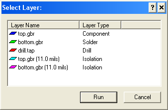
Select Mill->Run Layer from the menu bar.
Select the layer named "top.gbr (11.0 mils)" of type "Isolation"
from the table.
Click the
RUN
button.
|
(Click to enlarge)
|
| |
|
|

|
Warning
There are two layers named top.gbr. Be sure to select the one with the
type of "Isolation" not the one with type "Component."
If you choose the component layer, the mill will cut down the middle of the trace,
not around its border, and your board will be ruined.
|
|
| |
|
|
Monitor the run to insure that it continues to cut to the proper
depth.
If the board is warped, or there is a burr between the board
and the backing material, the depth of cut will be uneven,
leading to incomplete isolation.
A consistent track of yellow powder on the sides of the cut is
an indication that things are going well.
Its absence is an indication that the mill is no longer penetrating
the copper layer.
If this happens, stop the run, correct the problem, and restart.
|
| |
6. |
|
Turn the board over
|
| |
|
|
When the top layer isolation is complete, the spindle
motor
will turn off and the machine head will return to the home position.
Select Mill->Material Change from the menu bar.
Turn off the vacuum holddown by depressing the foot switch.
Remove the board and rotate it 180° about the axis formed by the two
tooling holes.
This will put what was the bottom of the board on top, with what was
the front of the board still at the front.
Replace the board, and click
Return to previous position
on the Material Change dialog.
Restart the vacuum pump with the foot switch.
|
| |
7. |
|
Set the contact target area for the bottom layer
|
| |
|
|
Choose Tools->ContactByTouch->Set target area(mirrored)
from the menu.
Click and drag the tool across a small area
chosen as for the top layer.
|
| |
8. |
|
Run the bottom layer
|
| |
|
|
If there is any doubt in your mind that you remembered to set the type
of the bottom layer to
Solder,
now is the time to resolve it. If the back of the board is not mirrored,
the cuts will be in the wrong place.
|
| |
|
|
Select Mill->Run Layer from the menu bar.
Select the layer named "bottom.gbr (11.0 mils)" of type "isolation"
from the table.
Click
OK.
Watch the first few cuts to insure that they are in the right place
and still of the correct depth.
|
| |
9. |
|
Drill the bottom holes
|
| |
|
|
Select Mill-Run Layer from the menu bar.
Select "bottom holes" from the list and click
OK.
The
Layer tool list
will appear.
Click
OK.
without changing any of the fields.
|
| |
|
|
When the run is complete, select Mill->Material Change
from the menu bar.
Turn off the vacuum pump.
|
| |
10. |
|
Inspect board
|
| |
|
|
Carefully examine your board to insure that all isolations have cut
completely through the copper and into the underlying substrate.
Make sure that all holes that are supposed to be in your board
have actually been drilled.
Check all corners for copper slivers, as described in the instructions on
soldering milled boards.
|
| |
|
|
Because the tooling holes precisely define the position of the board
on the milling table, you can remove and replace it and the milling
tool or drill will be able to return to exactly the same place.
This means that if you find a mistake before you cut out your
board, you can fix it by putting the board back in the machine
and recutting or redrilling the problem area.
|
| |
11. |
|
Turn things off
|
| |
|
|
Turn off the T-Tech machine and close the cover.
Close IsoPro and logoff.
If you are using a flash drive to store your board files, remember to remove it.
|
| |
12. |
|
Separate the boards
|
| |
|
|
Separate your boards
(or board) by cutting along the lines of 16 mil holes with
the the shear.
If you are very careful, you can line the board up by eye, but a much more
accurate way is to place two pieces of 28 or 30 ga wire in the furthest
separated holes of a row and use them as guides to align the row with the
edge of the lower blade of the shear.
|