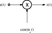
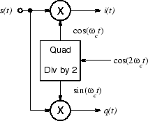
Our AM transmitter from Exercise 7 is straight out of the ELEC 241 textbook. In fact, there's no picture of the transmitter in the textbook, but if there were, it would look like this:

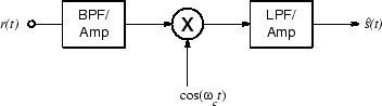
We can use the DDS from Exercise 8 to generate the local oscillator signal (cos(ωct)). We could try to use one of the mixers from Exercise 7 to do the multiplication, but neither of them is suitable for use in a receiver: the transformer coupled output will not pass baseband signals and the builtin crystal oscillator restricts tuneability. We could assemble another SA602 based mixer module with the proper combination of options, but since we are going to build a coherent demodulator, it will be easier if we use an I/Q mixer as our starting point.
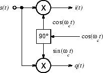
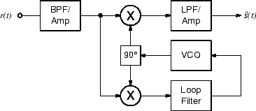
If the local oscillator is in phase with the transmitted carrier (i.e. if it is exactly equal to cos(ωct)) then the quadrature output of the I/Q mixer will be zero, since it is multiplying the received signal by sin(ωct). From ELEC 242 we know that a multiplier can be used as a phase detector. If we use a VCO as our local oscillator, and the quadrature half of the I/Q mixer as a phase detector, then we will have a phase locked loop which will synchronize the local oscillator to the transmitted carrier. Since the upper (in-phase) half of the mixer is multiplying the received signal by cos(ωct), then its output will be the demodulated signal. The resulting system is called a synchronous AM detector or a coherent demodulator.
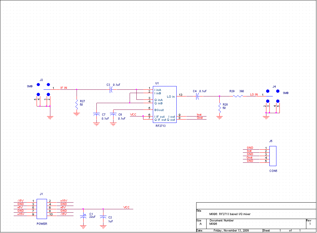
To build this we will need three new modules. The first is the I/Q mixer described above, based on the RF2713.
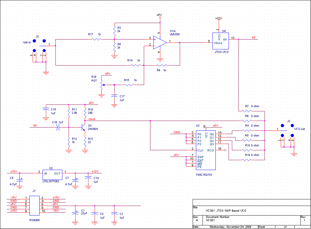
Next, we will need a VFO. Since we have software which converts the DDS into a VCO, we could use it, and we will try it as part of this exercise. But the relatively coarse quantization of the A/D converter in the MSP430 and the relatively low sample rate achievable makes the result a bit finicky. We will get a more robust (though harder to tune) result by using a conventional VCO manufactured by Mini-circuits. The lowest frequency version they sell covers the range of 12-25 MHz, so we will have to divide its output to get an appropriate frequency.
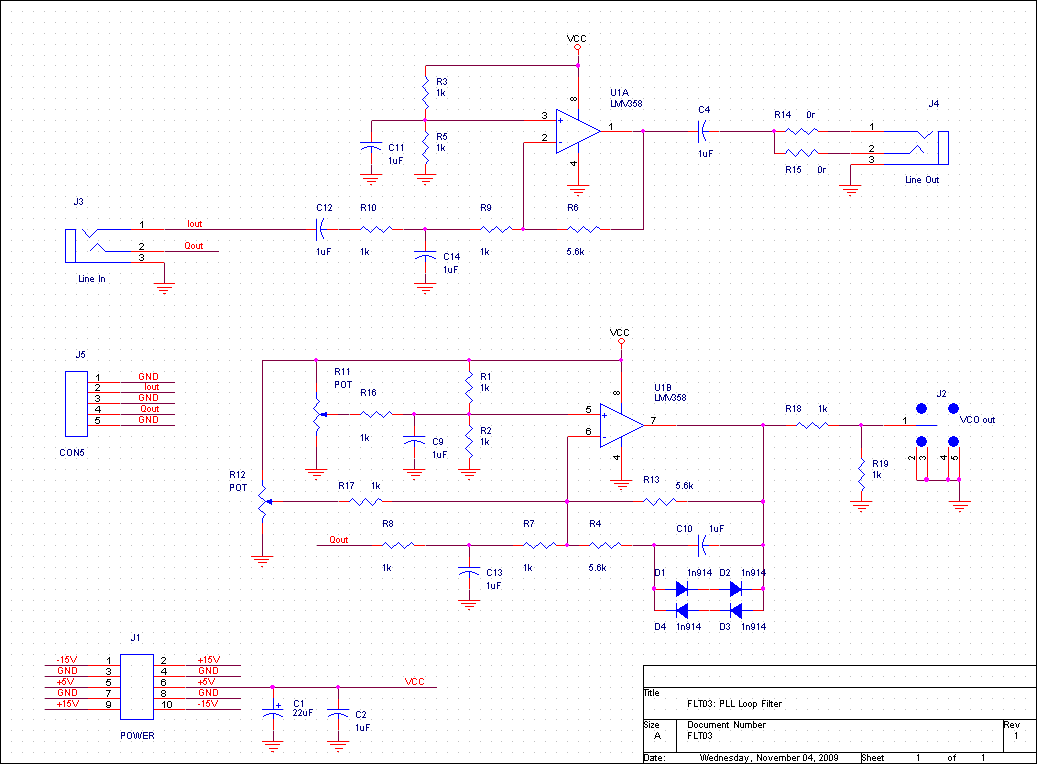
Finally we will need two filters, one for each branch of the I/Q mixer. We will make these out of op-amps so that we can also incorporate some gain.