(Click to enlarge)
Since we have decided to forsake the joy of assembling our own wireless communication system out of function level components in favor of the efficiency of buying & a system one ready to go on a single chip, our first order of business is to choose that chip. Due to the popularity of portable wireless devices, there are lots of candidates to choose from. Our choice, the Si4420 offers the following features:
Our chip comes in a 16-pin package. Two of those are used for power and ground, one for the crystal, and two more for the antenna. That leaves 11 pins for the interface. Although we can ignore a few of them, we need a minimum of 5 pins to make effective use of the chip. This means we could put the chip on a module by itself (like we have done with our other chips) and plug it into the 10-pin connector (J3) of the MSP430 module. This would leave the 5-pin connector (J4), with its two signals, to connect to the rest of our system.
If our goal was simply to study the radio chip, this would be the simplest approach. But if we want to incorporate a wireless data link into a larger system, having only two signals available to control everything else would be a significant limitation.
Another approach would be to build a module with both the radio chip and an MSP430 chip on it, bringing out the two left over signals. If those were enough, we could use this module by itself. If not, we could connect those two signals to our regular MSP430 module via J4 (which after all is intended to support a serial communication interface) and use its 5 signals (J3) to control the rest of our system. This is the approach we will use. This has an additional advantage: we can plug the RS323 module into one radio module and our MSP430 into the other, allowing a simple replacement of the serial cable with a wireless link.
For maximum flexibility, there are two 5-pin connectors on the radio module. One of them is connected to two of the I/0 pins of the on board MSP430 so we can do (almost) anything we want to with them, including using them as an SIO or I2C serial connection. The other 5-pin connector is connected to pins on the radio chip which provide direct connection to the transmitted/received binary signal, before any synchronization or assembly/disassembly into bytes is performed. This allows us to send arbitrary binary signals and to achieve accurate time synchronization between the transmitter and receiver.
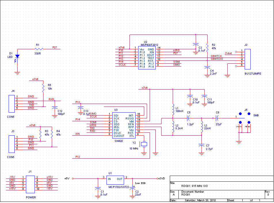
Put it all together and here's what we get:
J3 (on the left-hand edge of the module) connects to the two free pins on the MSP430. J4 (on the top-right of the module) connects to two pins on the Si4220 which carry the raw bit stream.