![\includegraphics[scale=0.500000]{ckt8.0.1.ps}](img54.png)
Many sensors, such as the dynamic microphone we used in ELEC 241 or the piezoelectric transducers we'll use in this exercise, produce an output voltage directly. Others, such as the carbon button microphone from 241 or the pressure sensor in this exercise, change their resistance in response to changes in the measured parameter. To produce a signal which we can process it is necessary to convert this change in resistance to a voltage.
One way to do this is with a voltage divider:
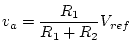 .
If we consider the sensitivity of the output voltage
.
If we consider the sensitivity of the output voltage 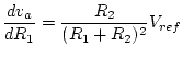 .
For small changes (
.
For small changes (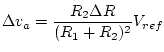 If
If 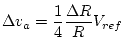 .
.
If the internal reference voltage for the MSP430 A/D converter
is set to 2.5 V, the minimum resolvable change in voltage
will be about 2.4 mV.
This means that the smallest change in resistance that we can
measure is
 or about 0.39%.
This doesn't seem like much of a limitation, but the pressure
sensor we will be using
has a full-scale
resistance change of only 0.25%,
so we would be unable to measure any changes.
or about 0.39%.
This doesn't seem like much of a limitation, but the pressure
sensor we will be using
has a full-scale
resistance change of only 0.25%,
so we would be unable to measure any changes.
The root of the problem is that the total change in the voltage
![]() is only a small fraction of the range of the A/D converter.
But since this value is located in the middle of the range,
we can't amplify
is only a small fraction of the range of the A/D converter.
But since this value is located in the middle of the range,
we can't amplify ![]() without exceeding the range of the
A/D converter.
What we need to do is amplify the
changes
in
without exceeding the range of the
A/D converter.
What we need to do is amplify the
changes
in ![]() about its nominal value.
about its nominal value.
Suppose that we add a second voltage divider to the above circuit:
![\includegraphics[scale=0.500000]{ckt8.0.5.ps}](img56.png)
One circuit that will
amplify ![]() ,
is
the difference amplifier:
,
is
the difference amplifier:
![\includegraphics[scale=0.500000]{opamps/diff2.ps}](img57.png)
![\includegraphics[scale=0.500000]{ckt8.0.3.ps}](img58.png)
For this circuit
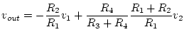 .
If
.
If
![]() and
and ![]() , then
, then
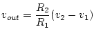 .
But if the resistances aren't exactly matched, we will have
different gains for the inverting and non inverting inputs.
Suppose that
.
But if the resistances aren't exactly matched, we will have
different gains for the inverting and non inverting inputs.
Suppose that
![]() .
Assume that
.
Assume that ![]() is the larger of the two and that
Let
is the larger of the two and that
Let ![]() be the average of
be the average of ![]() and
and ![]() and let
and let
![]() .
Then
.
Then
![]() or
or
![]() .
.
![]() is the
differential gain
and
is the
differential gain
and ![]() is called the
common-mode gain.
The
common-mode rejection ratio
(CMRR) in decibels is defined as
is called the
common-mode gain.
The
common-mode rejection ratio
(CMRR) in decibels is defined as
![]() .
.
The following circuit combines high input impedance, high common mode rejection, and single resistor gain programming. It is often referred to as the "three op amp" or "classic" instrumentation amplifier.
![\includegraphics[scale=0.500000]{ckt8.0.4.ps}](img59.png)