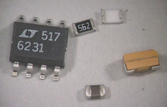
The value code on a surface mount resistor is the same as that on a leaded resistor, except that numerals are used rather than colored bands. For example, the "562" code on the resistor above denotes 56x102 or 5600 ohms. Electrolytic capacitors use the same code with the value in pF, so your 22 µF capacitor should be labeled "226". Ceramic capacitors are unlabeled.
It is possible, and often necessary, to mix thru-hole and surface mount components on the same board. Our final components, the BNC jacks, are thru-hole components.
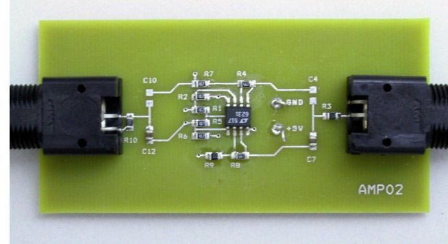
When it's all finished, your board should look like this (from the top):
Another advantage of surface mount technology is that you can use both sides of the board. Most of the capacitors are on the bottom of the board, which looks like this when finished:
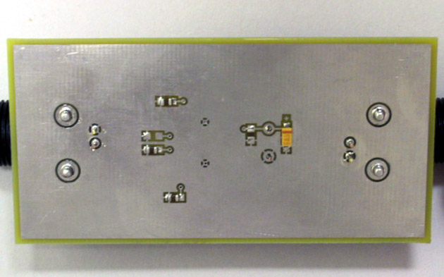
Note that both of these photographs are of a board configured to use the non-inverting amplifier.
We have several styles of tweezers, including broad tipped, straight fine point, and curved fine point. Choose whichever suits the particular situation (or your style) best.
The tips are very easy to change: First turn off the power (changing the tips with the power on can damage the heating system). Grasp the tip with the black silicone pad (tethered to the iron's cord) and pull gently. Place the hot tip in one of the grooves on the side of the stand to cool, select a new tip, and press it firmly in place. DON'T use pliers to change the tips.
For more information, see the PS-800 User Manual.
It does have at least two things going for it: It will turn itself off if left unused for a certain amount of time, and it supports a very nice pair of thermal tweezers (WMRT).
Like the Xytronic, and unlike the OK, it provides continuously adjustable tip temperature. However, since the WD2M is a two-channel unit, but only has a single display, some deft finger work is necessary to utilize this feature. To select the channel to be displayed, press either the button labeled "1" (for the soldering iron) or "2" (for the thermal tweezers). Immediately after a button is depressed, the display shows the "set" temperature. After a few seconds, the display changes to show the actual current temperature. To change the set temperature, use the up and down arrow buttons. Use of either of these buttons also changes the display to the set temperature for a few seconds.
The tips on the WMP iron are threaded, rather than press fit. To change tips, turn off the iron, grip the tip either using the black silicone pad from the PS-800 or the rubber handled socket wrench (normally stored in the back of the WMP stand), unscrew it, and place it in the rack. Select the new tip, slide it on, and screw it in firmly, but not too tightly. If you use the socket wrench, remember that by the time you have removed the old tip and placed it in the rack, the metal portion of the wrench will be almost as hot as the tip you removed.
For detailed instructions, see the WD2M User Manual.
The best tip to use will have a broad, flat surface to provide maximum contact area between the tip and the joint. Tips of this type include chisel shaped tips, with two flat faces, and beveled tips with just one. Unfortunately, it is not possible to make chisel tips smaller than about 1 mm. Where a finer tip is required, conical tips are available with points as small as 0.25 mm.
We have spools of wire solder in two sizes: small (0.015 in. dia.) and medium (0.030 in. dia.).
All of the fluxes we have are of the no-clean variety, which means that the flux residue can be left on the board without undesirable effects. If you find the flux residue esthetically offensive, it can be removed, using either isopropyl alchohol or the can of aerosol flux remover. If you do decide to remove the flux, be prepared to do a very thorough job. Simply spraying some flux remover on the board and scrubbing it around with the brush will leave big streaks of flux all over the board, rather than small spots of flux on the joints.
It's important not to set the flow rate too high. On a crowded board it's possible to literally blow away a swath of components which you had not intended to remove. For the small, angled tip, the minimum rate (1) is about right. For the large round tip, try a setting of 3 to 3.5. The temperature should be set to about 340°C. For more information, see the 850D Instruction Manual.
Now that we've been introduced to the cast, it's time for the show to begin. The plot is very simple: take all of the components out of the bag and solder them onto their proper places on the board.
Unlike thru-hole components which stay put while you're soldering them, surface mount components will slide around until at least one of their leads is soldered to hold it in place. To avoid the need for three hands (one to hold the component (with tweezers), one to hold the iron, and one to hold the solder), we use a three step procedure. First we apply the necessary amount of solder to one of the pads (solder in one hand, iron in the other). Next we remelt the solder and hold the component in place till the solder resolidifies (tweezers in one hand, iron in the other). Finally, with the component firmly held in place by this first pin, we solder the remaining pin(s) in the conventional manner (solder in one hand, iron in the other).
While this is simple enough in theory, in practice there are some subtleties involved which are probably best seen rather than read about. To see this process in action, you can watch the SMD Soldering Video.
Ideally, once you've soldered all of the components onto your circuit board, it will work correctly the first time and will continue to work for years to come (or at least until the end of the semester). In reality, mistakes will be made, components will be defective or will fail, and it will be necessary to remove components from the board and replace them with new ones. This will require us to undo the previous soldering, or unsolder the wayward components.
Although we have to solder the components to the board one pin at a time, we need to remove them by unsoldering all the pins simultaneously. Most techniques for removing SMDs one pin at a time run the risk of lifting a pad. To see examples of these unsoldering techniques, watch the SMD Unsoldering Video.