As stated in the Goals section, there are four major goals for this week's Exercise. We will cover layout and fabrication in this section and assembly and test in the next. Since several days will be required for the fabrication of your board, this is a natural separation.
You have a total budget of $102 for this Exercise.
There are a number of PC CAD packages available, both free and commercial. Here are a few of your choices:
Orcad is a large, powerful, and complex EE CAD package. It's also very expensive if you have to buy it, but fortunately Rice has a site license. It is available on the Windows 2000 machine on the southwest bench.
Eagle is another commercial PC design package. The full version is fairly expensive, but a free, limited function version is available. Eagle has been installed on the machine on the northeast bench.
ExpressPCB provides free PC layout software for use with their fabrication service. In fact, you must use this software to use their service, and it has a non standard output format which is not accepted by other board manufacturers.
There are a number of free, open-source PC layout packages available. Kicad and gEDA were developed for Linux, but Windows binaries are available. FreePCB is a Windows program, but will run on Linux under Wine.
Tutorials for most of these packages may be found in the Fabrication section of the Lab Textbook, along with a couple of tutorials on the overall PC design and layout process.
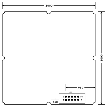
To allow your board to be plugged into the DRB, you should use the board outline and power connector location shown in the drawing below (dimensions in mils). The notches in the corners and sides have a radius of 62 mils.

Place bypass capacitors as close as possible to their chips. The bottom of the board, directly underneath the chip, is often a convenient location.
The power and ground pins for the FST3253 and the 74AC74 are not shown on the schematic, but should be automatically connected when the components are placed. Verify that these pins are indeed correctly connected on your layout.
It is not possible to lay out this circuit without crossovers. These can be done by routing some traces on the back of the board, by using discrete wire jumpers, or a mixture of both. In terms of signal integrity, it is best to use jumpers and to install them on the back of the board.
More information on proper circuit layout may be found in the Layout of the Lab Textbook.
The company with which the ECE Department has had the most experience is PCB Express. They are not the least expensive, but they are fast and reliable. Their lowest price service is $95 for a batch of two boards of up to 9 square inches (which will just fit the 3x3 inch Digital Radio Breadboard form factor), with 24 hr turn around. These are double sided boards with no silkscreen or solder mask. The price for up to 19 square inches is $143, so if you and another group were to combine your two designs onto a single board, the cost would be $71.50 per design (but you will have to cut the two sub-boards apart yourself).
A lower price is available from ExpressPCB. You can get 3 3.8 x 2.5 inch boards for $51. These are also double sided, no silkscreen, no solder mask, 1 day turnaround. To use this service, you must use their (free) proprietary software. They do not accept Gerber files. Although you cannot fit the entire 3 x 3 inch DRB module into this form factor, you can get 5/6 of it by leaving out the top half inch, which should be sufficient for this circuit.
Advanced Circuits has a $33 each special for two layer boards up to 60 square inches, with solder mask and silk screen. The lead time is five days. The minimum quantity is normally four, but this is waived if you are a student (i.e. you can order a single board for a total cost of $33 plus shipping).
As with ordering parts, Mr. Dye will handle the process of submitting and paying for your board run. And, as is the case with parts, your PC job must be approved by the instructor before Mr. Dye will send it out.