Our plan for this week is to
combine the analog RF processing of the Ten-Tec RX320
with digital IF processing in Labview.
Although the RX320 is a complete receiver on its own,
it only supports
AM, SSB, and Morse Code (CW) signals.
| |
|

|
Setting up. |
|
The
RX320 must be connected to the PC in order to function.
If not already set up,
connect the PC serial port to the
SERIAL DATA
connector.
Connect the external antenna to the
ANTENNA
connector
and plug one of the speakers into the
EXTERNAL SPEAKER
connector.
Start the Ten-Tec Radio Contol Panel program
(Programs->Ten-Tec PC RADIO->Ttrcx).
|
Listening. |
|
There's no instruction manual for the RX320, but the online
help gives a quick tour of the functions.
The quickest way to set a new frequency is to left click on the
frequency display (the large yellow numbers) and type the desired
frequency (in MHz), followed by return.
If you are tired of listening to AM broadcast stations,
a reliable station to try is WWV, the NIST time service
at 5, 10, and 15 MHz.
15 MHz will be the strongest frequency during daylight, and 5 MHz can
usually be heard only late at night.
Strong AM signals can also be found on the international broadcast bands.
There's a list of international broadcast and amateur frequencies under
Introduction->Listening to the World
in the RX320D help file.
Again, frequencies above 10 MHz will be best during the day,
those below best at night.
|
Characterize RX320 response. |
|
Using the appropriate adapter, connect the RX320
I.F. Out
to the scope (with a BNC-T) and the spectrum analyzer.
Configure the spectrum analyzer as follows:
- Center Frequency
-
12 kHz
- Span
-
24 kHz
- Level
-
-20 dBm
Set the RX320 mode to AM, and tune to 9 MHz.
With the RF off, set the signal generator to:
- Frequency
-
9.0 MHz
- Amplitude
-
-100 dBm
- Modulation
-
AM, 80%, INT 400 Hz, Modulation ON.
Connect the signal generator output to the RX320
ANTENNA
input.
Turn on the signal generator RF output.
You should be able to hear the 400 Hz tone
and see a peak at 12 kHz on the spectrum analyzer.
Turn the modulation off.
Reduce the signal generator output until you can barely see the
12 kHz peak. This is the minimum detectable signal (MDS) level.
Increase the signal generator output in steps of 5 dBm until
you reach an output of 0 dBm.
At each step, note the output level shown on the spectrum analyzer.
Make a plot of the output vs. input level.
Note the point at which the output stops increasing with increasing
input. This is the AGC (automatic gain control) threshold.
Reset the spectrum analyzer to 24 kHz center frequency, 48 kHz span,
-20 dBm reference level.
Set the signal generator output to -80 dBm.
Increase the signal generator frequency in steps of 1 kHz,
noting the amplitude of the spectrum analyzer peak at each step,
until the peak is no longer visible.
Make a plot of the frequency response.
What is the IF bandwidth?
|
| |
|
|
Connecting the RX320. |
|
Reset the signal generator to 9.0 MHz, -80 dBm,
and turn the modulation on.
Disconnect the RX320
I.F. OUT
from the spectrum analyzer and connect it to the NI 6251 A/D input.
Connect the 6251 D/A output to one of the speakers.
|
The Labview Radio VI. |
|
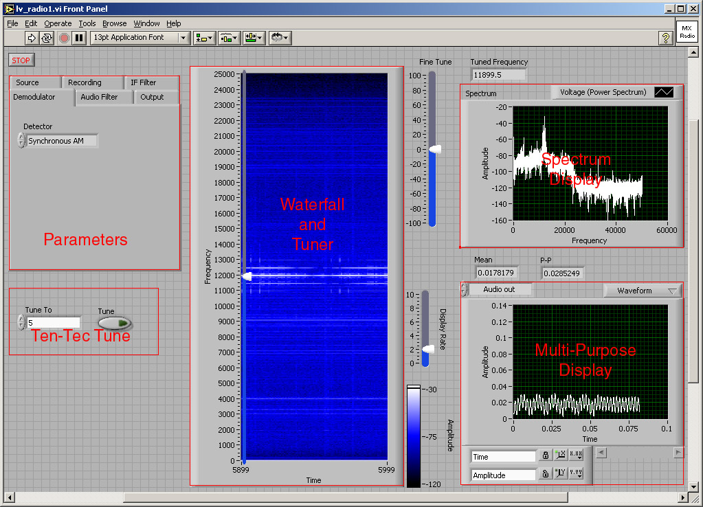
Load the lv_radio1.vi file from the directory C:/432/lv_radio.
 The waterfall and spectrum displays are similar to the ni_proc VI used in the
previous two labs.
The Multi-Purpose Display shows the waveform or spectrum at selectable points in
the
system.
Except for the tuning controls, all other controls are in the set of tabbed
panels marked "Parameters" in the screen image above.
Each panel contains the controls for the corresponding block in the block diagram.
Examine the block diagram and note where the controls are connected.
The waterfall and spectrum displays are similar to the ni_proc VI used in the
previous two labs.
The Multi-Purpose Display shows the waveform or spectrum at selectable points in
the
system.
Except for the tuning controls, all other controls are in the set of tabbed
panels marked "Parameters" in the screen image above.
Each panel contains the controls for the corresponding block in the block diagram.
Examine the block diagram and note where the controls are connected.
|
Tuning |
|
Receiving a signal requires setting two tuning frequencies:
the first local oscillator in the RX320 front end, and the last
local oscillator in the Labview VI.
To tune the RX320, enter the desired frequency in the
Tune To
box (in the Ten-Tec Tune block) and press the
Tune
button.
If the frequency of the desired signal is a multiple of 2.5 kHz, then
it will appear at 12 kHz in the lv_radio IF,
otherwise it will be necessary to offset the VI's tuning frequency
appropriately.
The main tuning control has been overlaid on the waterfall display.
This makes it easy to tune to a signal which has been identified on the waterfall.
This is especially useful for tuning single sideband (SSB) signals.
The main tuning control tunes in steps of 50 Hz and the fine tuning control
tunes continuously 100 Hz to either size of this value.
|
Listening to the signal generator. |
|
Start the VI, tune to 9.0 MHz, and turn on the RF output of the signal
generator. You should hear the tone from the speaker and see the carrier and
sidebands on the spectrum and waterfall displays.
Use the multi-function display to trace the signal through the processing
chain. Try all of the AM demodulators and experiment with the IF and AF filters.
|
FM. |
|
Set the signal generator to FM, with 400 Hz modulation and 4 kHz deviation.
Set the demodulator to
PLL FM.
Vary the modulating frequency and the deviation and observe how the spectrum
changes. How accurate is our rule of thumb regarding the bandwidth of an FM signal?
|
Listening to real radio signals. |
|
Disconnect the signal generator, connect the antenna, and go in search of
signals to demodulate.
As mentioned above, AM signals should be plentiful, but finding some of the
others may take a bit of work.
When listening to AM signals, compare the performance of the three
different demodulators (envelope, product, and synchronous AM).
One fairly reliable signal is the New Orleans Coast Guard weather station
at 8.502 MHz. This station alternates between voice announcements in
SSB and FAX images in FSK. It transmits regularly, but not continuously,
during the daytime. Voice weather anouncements in SSB can sometimes also be heard
at 15.034 MHz.
There aren't very many FM signals below 30 MHz, but there are plenty of
FSK signals, which are just binary FM. Use the FM demodulator with the
AF filter bandwidth set fairly low.
The 12 MHz band has a number of FSK signals, as well as other digital signals.
Some frequencies to try are 12.015 and 12.120.
|
Listening to recorded signals. |
|
If you can't find any interesting signals on the air, here are a few pre-recorded
ones to use instead, located in the C:/432/signals directory.
- DATA5.SCL
-
FSK fax
- DATA10.SCL
-
SSB voice
- DATA13.SCL
-
FSK data
|
Your task is to
design and build a sub-VI which
separates and counts the 1-second ticks from the WWV signal.
Your design should work reliably as the received signal strength varies due
to changes in propagation conditions.