When we mix two real sinusoids (i.e. multiply them together),
we get two new, real sinusoids, one at the sum of the original frequencies
and the other at the difference:
cos(ω1t)
×
cos(ω2t)
= ½ cos((ω1 + ω1)t)
+ ½ cos((ω1 - ω1)t)
In the conventional superheterodyne architecture
this gives rise to images which must be eliminated by filtering the RF
signal before mixing.
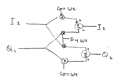
If our signals are complex exponentials rather than real sinusoids,
we can shift frequencies without introducing images:
ejω1t
×
ejω2t
=
ej(ω1+ω2)t
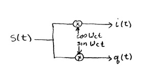
Starting with a real baseband signal s(t),
we can shift it up to a carrier frequency ωc by using the I/Q
modulator.
Since
ejωct =
cos(ωct) + jsin(ωct)
then
i(t) = s(t)cos(ωct)
is the real part of s(t)ejωct
and
q(t) = s(t)sin(ωct)
is the imaginary part.
I.e., i and q together represent a complex signal as a pair of real signals.
The circuit which produces i and q is called a
quadrature modulator
or a
half-complex mixer.
The choices for transmitter architecture largely parallel those for receivers. These include:
The frequencies we can directly or harmonically generate are so low that efficient radiation is impossible with a reasonably sized antenna, as we saw in Exercise 2. Direct modulation provides a very simple transmitter for AM or DSB, but for SSB and some other modulation schemes, it will be necessary to use a quadrature modulator. In this case, we might as well add a few more parts and use a low-IF, image reject architecture. This has the added advantage of allowing AC coupling in the analog circuitry.
The transmitter we will built this week will use a superheterodyne architecture, similar to last week's receiver, but with the signal flowing in the opposite direction. Two significant differences: We will use single, rather than triple conversion; and, to avoid the need for image reject filtering, we will have to use complex, rather than real, signals. We will continue to use a 12 kHz IF, but we will upconvert directly from a complex IF signal to the transmitted signal using a quadrature modulator.
The specific architecture we will use
is a variation of the
Weaver modulator,
which was originally developed as a method of SSB generation.
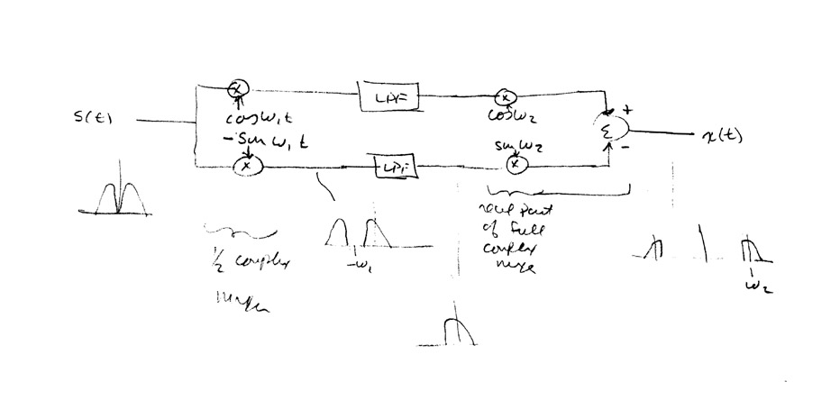
In our transmitter, instead of shifting the input signal down by a small amount, we will shift it up to our intermediate frequency, i.e. 12 kHz. This will be done digitally by multiplying by cos(ωIFt) and sin(ωIFt). The resulting I and Q components of the IF signal will be converted to analog signals and sent to an analog quadrature mixer where they will be multiplied by in-phase and quadrature square waves of frequency ωLO = ωc - ωIF. This multiplication will be performed in a commutating sampler where the switching signals are derived by dividing down a clock of frequency 4ωLO.
Here's the circuit of our analog quadrature mixer:
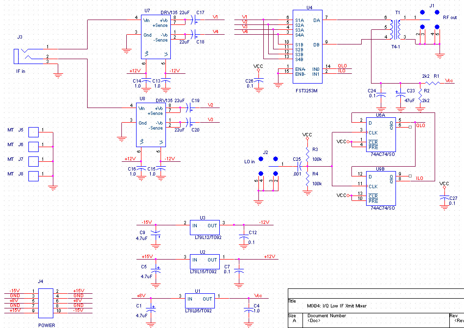
And here are the data sheets for the ICs in the circuit: