ELEC 432
In the Lab
Now that we have the concepts of I/Q modulation and complex signals under control,
our task is to realize these concepts in hardware, verify that they really work,
and incorporate the hardware with appropriate software to make a transmitter.
Since our final signal will be at a much higher frequency than we we were able to
produce with direct D/A conversion in Exercise 2, we should be able to get much better
performance (i.e. longer range) with our small whip antenna.
Our transmitter is divided into two parts, one
using DSP in software and the other
using analog processing in hardware.
The DSP portion is implemented in the VI
lv_xmit.vi.
This VI and its subVIs are in the directory c:/432/lv_xmit.
lv_xmit is similar to the lv_radio VI we used last week, but with the
direction of signal flow reversed, going from an input at baseband to an output
at an IF of 12 kHz.
With lv_radio, the Ten-Tec RX320 handled the conversion from the desired receive
frequency to the 12 kHz IF.
Since we can't easily reverse the signal flow direction in the RX320 (and since we
will need it to receive our transmitted signals) we will have to provide other
hardware to upconvert from the 12 kHz IF output of lv_xmit to the desired
transmit frequency.
This conversion will be performed by a quadrature mixer.
The best choice for the D/A output device would be the sound card, since it has
a very effective output anti-aliasing filter, while the NI 6251 has no filtering.
Unfortunately, the Labview sound card driver and the Express VIs don't get along very well,
resulting in an annoying ticking in the output when the two are used together.
We could build a simple transmitter using the sound card,
but to achieve all the features we want, we
will have to use the NI card for reliable operation.
This means we will have to build our own anti-aliasing filters, but if we continue
to sample at 100 kHz for a 12 kHz IF, the requirements aren't too stringent.
Part 1: Building the Transmitter
| |
|

|
New hardware components. |
|
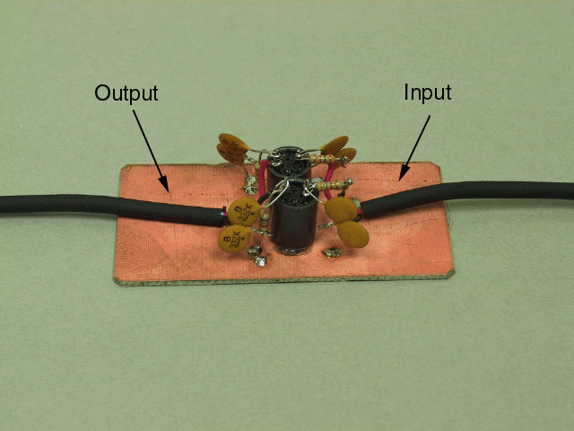
The central character in this week's production is the Quadrature Modulator
that you built in Exercise 4.
We also have two filters. The first is a 24 kHz, 3-pole Butterworth lowpass
filter to remove aliases from the D/A output.
Because this filter connects a low-impedance output to a high-impedance input,
it is not symmetric, so it is important to distinguish between the input and the
output.
This module has been built using
ugly construction,
where components are soldered directly to a solid ground plane.
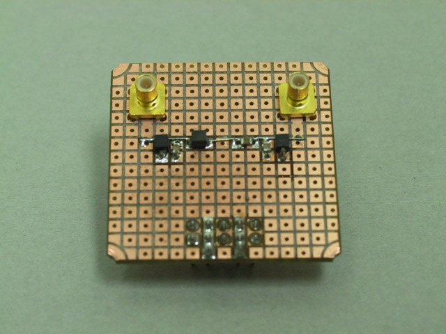
The second filter is a 6-pole Butterworth bandpass filter with a center frequency of
13.5 MHz and a bandwidth of 3 MHz, used to filter out the images produced by
the harmonics of the square wave local oscillator.
(This circuit is symmetrical, so either connector may be used as the input.)
This module was built using a modified version of the
Ivanboard..
In this style of construction, the top side of the board consists of an array of
square pads on 0.1 in. centers, and the back side is a solid ground plane.
Surface mount components are soldered to the pads, and connections to ground are
made by drilling a hole and soldering a wire from the pad to the ground plane.
This board (also made on our PC milling machine) has had all the holes pre-drilled.
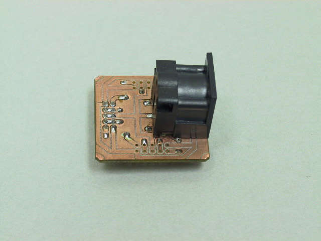
Since the modulator circuit contains active devices, we need to provide power to
the breadboard. Our final new module is the power connector, which accepts a cable
from the power supply.
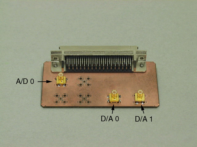
We also have a slight modification to one of the existing components.
The DAQ module now has connectors for both of the D/A outputs.
|
Connecting power. |
|
Verify that the banana plugs on the Digital Radio Breadboard power cable are
connected to the power supply as shown in the picture:
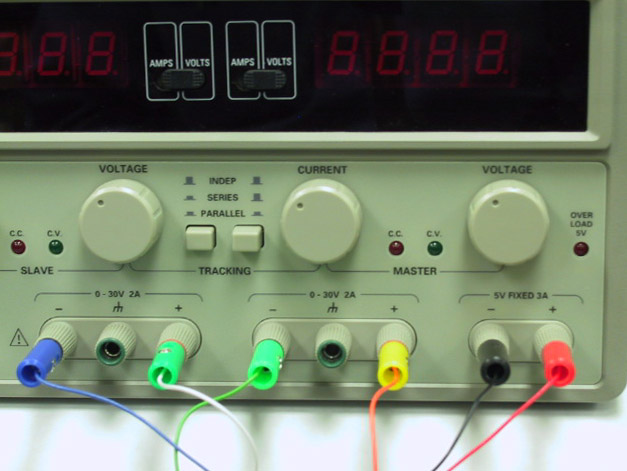
Unplug the cable from the Digital Radio Breadboard power connector,
turn on the power supply, and verify that both outputs are set to 12.0 V.
Turn off the power supply and reconnect the power cord to the breadboard.
|
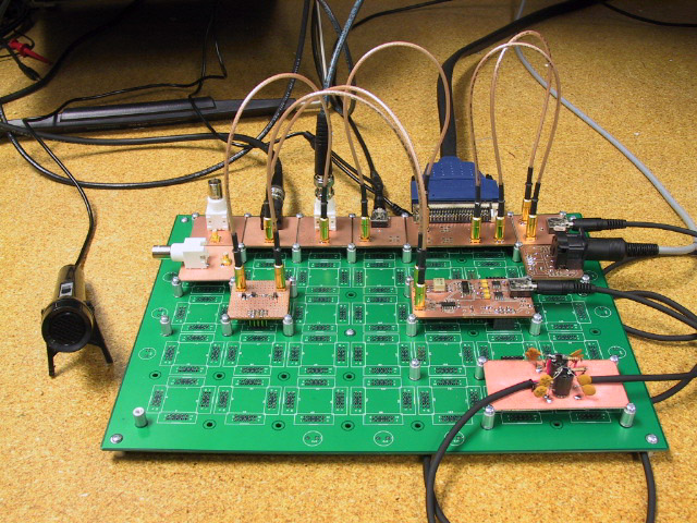
Connecting the components. |
|
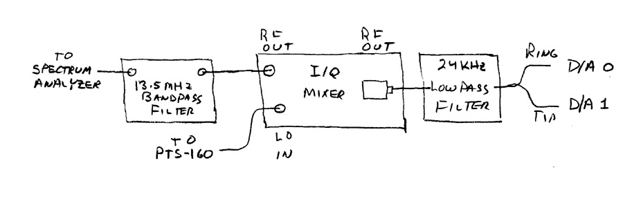
Connect the modulator, the two filters, and the D/A outputs as shown in the diagram.
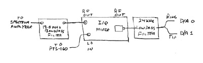
This picture below shows one way of doing it.
|
Connecting the instruments. |
|
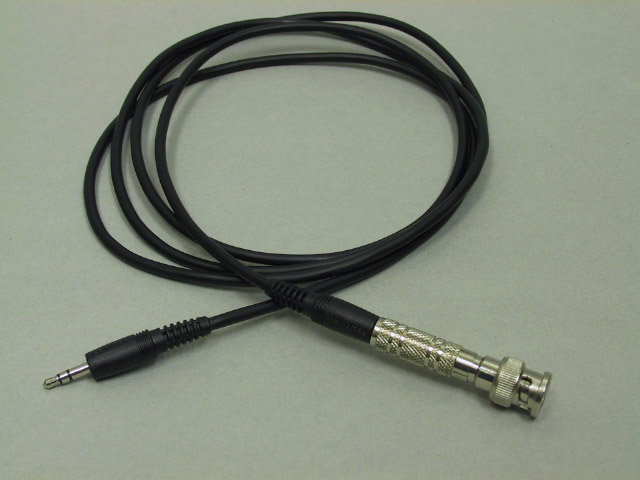
Using the
BNC to phone plug cable
connect the function generator output to the A/D input.
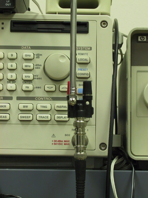
Put BNC T connectors on the scope and spectrum analyzer inputs.
Connect the RF output to the scope, the spectrum analyzer, and a whip antenna.
The figure below shows a fairly stable way to mount the antenna.
Connect the rear-panel output of the PTS-160 frequency synthesizer to the
LO input of the mixer.
|
Setting up the instruments. |
|
Configure the spectrum analyzer as follows:
|
Frequency:
| 13.56 MHz
| |
Span:
| 100 kHz
| |
Level:
| 20 dBm
|
Set the PTS-160 to 54.192 MHz, 0.4 V output.
|
Part 2: The lv_xmit VI
| |
|
|
Set up the VI. |
|
Load lv_xmit.vi, located in c:/432/lv_xmit.
The layout is essentially the same as last week's lv_radio.
Set the parameters as follows:
|
Source:
| Function Generator
| |
AF Filter:
| Off
| |
Modulation:
| AM
| |
First Mixer:
| NCO
| |
IF Filter:
| Off
| |
Output:
| 6251 D/A
|
|
Initial test. |
|
Set the function generator to produce a 1 kHz sine wave.
Set the output level to zero
and start the lv_xmit VI.
With no input, only an unmodulated carrier will be produced.
If everything is set up correctly, you should see a large peak
on the spectrum analyzer at 13.560 MHz
and perhaps a few smaller peaks.
If the large peak is at 13.536 MHz, reverse the two D/A output channels.
|
Balancing amplitude and phase. |
|
In addition to the carrier peak at 13.560 MHz, there will probably
be a smaller peak at 13.536 MHz.
This is the incompletely cancelled lower sideband, caused by imbalance
in the gain and phase of the I and Q paths of the mixer.
By adjusting the amplitude and phase of one of the outputs of the VI, we
can compensate for this and achieve nearly complete cancellation of the
unwanted sideband.
Alternately adjust the
Amplitude
and
Phase
sliders on the
First Mixer
parameter panel until this peak is minimized.
|
Transmitting test. |
|
Set the oscilloscope time base to 0.5 ms/div.
Increase the output level on the function generator while watching the RF output
on the scope.
You should see the classic amplitude modulation waveform.
Adjust the function generator level until the signal is almost fully modulated
(i.e. doesn't quite go to zero in the troughs).
Tune the Kaito radio to 13.56 MHz and you should hear the tone
(even with the receiver antenna more than a few inches from the transmitter).
|
AM radio station. |
|
Unplug the function generator and plug in a microphone.
On the
Source
panel, set the
Input
to
Microphone,
and try out voice transmission.
What is the range of your station?
|
Part 3: An SSB transmitter
The original Weaver modulator shifted the audio spectrum downward by half the bandwidth,
used a low pass filter to remove the unwanted sideband, then shifted the remaining
sideband up to the transimtting frequency.
Since Labview does all the work for us, bandpass filters are just as easy to design
and implement as lowpass, so we can use a bandpass filter at the IF frequency to
filter out the appropriate sideband.
To produce a single sideband signal, we need to do two things:
remove the carrier and remove the unwanted sideband.
The way our transmitter is constructed, this will be done in two separate steps:
the carrier will be removed by switching the modulation from
AM to DSB, then the sideband will be selected by filtering the IF.
| |
|
|
Set up the Ten-Tec receiver. |
|
Plug a speaker into the RX320
EXTERNAL SPEAKER
output
and connect a BNC-Banana adapter to the
ANTENNA
input (at this range we need a very small antenna to prevent overload).
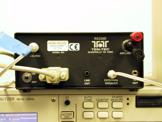
Load the
Ten-Tec Radio Contol Panel program (Programs->Ten-Tec PC RADIO->Ttrcx).
Tune to 13.56 MHz and select
AM
mode.
With the transmitter still set for
AM
modulation,
verify that you can still receive your transmitter.
|
SSB voice transmission. |
|
Set the
Modulation
to
DSB,
and the
IF Filter
to
USB.
With the receiver still set to
AM,
speak into the microphone.
The received signal should sound very distorted.
Switch the receiver to
USB
and, voila, intelligible speech.
Because of frequency differences between the various pieces of equipment, it may be
necessary to slightly retune the RX320 for maximum fidelity.
|
Part 4: A Design Problem
The current version of lv_xmit allows us considerable flexibility in
transmitting analog signals (e.g. voice), but its digital data transmission
capabilities are rather limited.
By fiddling with the various parameters, we can send binary signals using
OOK, BPSK, and FSK, but currently our only source of binary signals is
a square wave (using the
Pulses
input).
Your task is to create a signal source sub-VI that will generate a more
interesting binary signal than the square wave.
In particular, your VI should send the message "VVV" once every five seconds
(the letter "V" is the traditional symbol for transmitter testing).
Your VI should have the option of transmitting the message using
Morse code (at 10 WPM) or ASCII (at 50 BPS).
(If you don't remember the Morse code symbol for "V", just hum the first
bar of Beethoven's 5th symphony.)
Since Morse code is self synchronizing while ASCII is not, your ASCII message
should contain some means to allow synchronizing the receiver with the transmitter.